Week 06: Electronics Production
This week our assignments were to:
- Characterize the design rules for the PCB production process at the Aalto Fablab.
- Make an in-circuit programmer. Create tool paths for the milling machine, mill it and stuff (solder components) the board.
- Test the board and debug if needed.
- Document the process in a new page on your documentation website using pictures and text.
- Submit the link of the page.
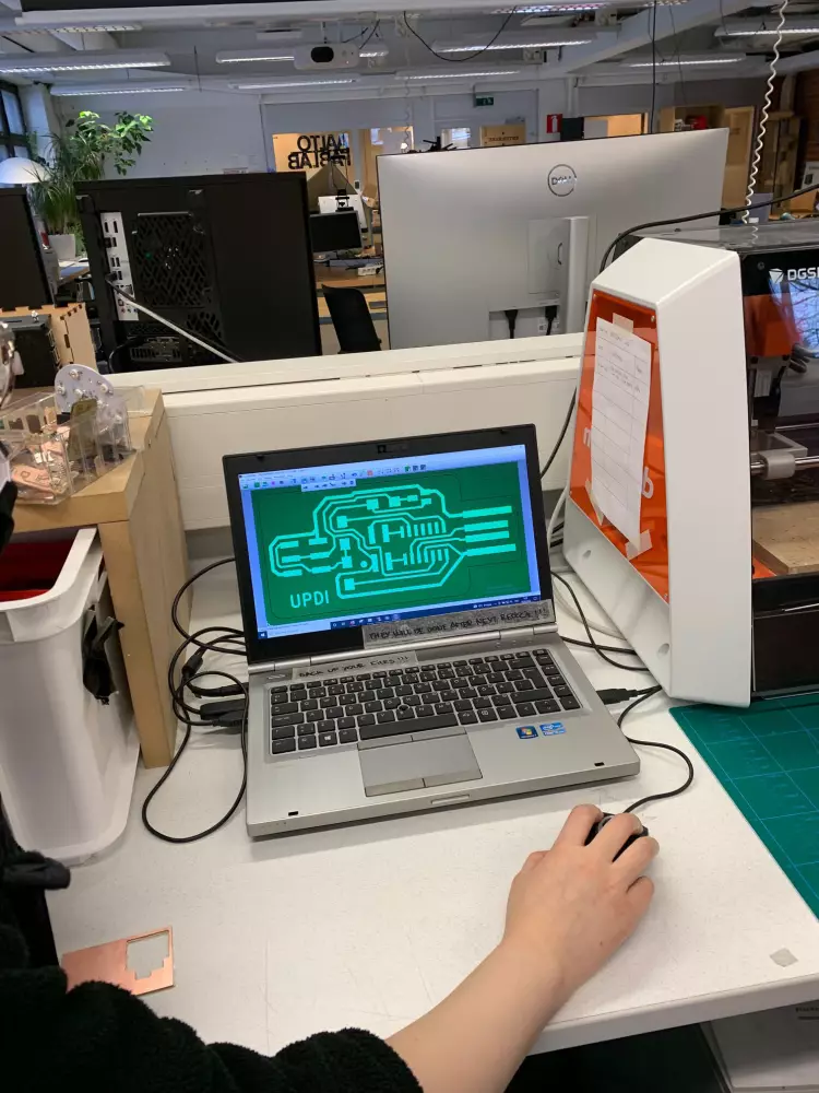
PCB Milling
PCB milling is a process in which material is removed from a one- or two-sided copper plated fiber material to produce a PCB.
To start this process, one needs to design a PCB, for example in KiCad. In our exercise, this step had already been taken care of, so we only had to prepare the designs for milling and mill the PCB.
To prepare the files for milling, we used a program called CopperCAM. In this program one can visualize what the engraving result will look like, and fix all possible errors.
To begin the process, we did a bunch of boiler plate work to insert our material and tool properties. Let's start with stuff regarding the material and the design file:
-
In
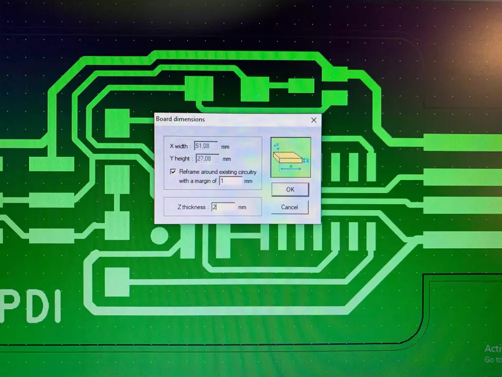
File > Dimensions:- Set
Marginto1 - Set Z thickness to
2for one-sided material,2.1for two-sided. This is with our FR1 boards that have a thickness of 1,6mm.
- Set
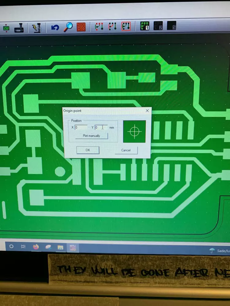
- In
File > Origin:- Set origin to
0,0
- Set origin to
Next up we can adjust parameters regarding the tools. To view available tools, you can go to Parameters > Tool library. At the Aalto Fablab we have the following milling bits available:
- .1-.15mm engraver
- .20-.50mm engraver. We will be using this to mill the tracks for our UPDI programmer.
- 1mm cutter. We will be using this to cut out our programmer from the copper board.
In addition to these bits there are a few different drill bits used to drill holes for through-hole vias as well as mounting holes.
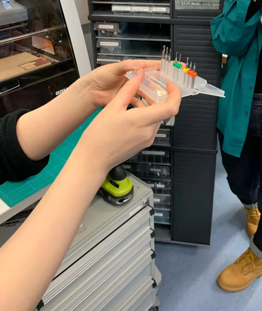
Engraving bits at the Aalto Fablab have a orange ring around them, while the cutter bits have a yellow ring. Drill bits either have a green ring or don't have a ring at all.
To set up the tool properties, we go to Parameters > Selected tools:
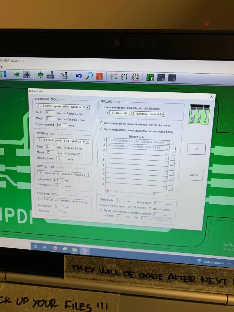
- For the .20-.50mm engraving tool we set the depth to
0.1and the speed to10mm/s. - For the cutter, the depth is
2mmor2.1mmdepending on the Z thickness. The speed is the same as the engraver at10mm/s
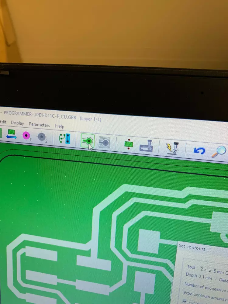
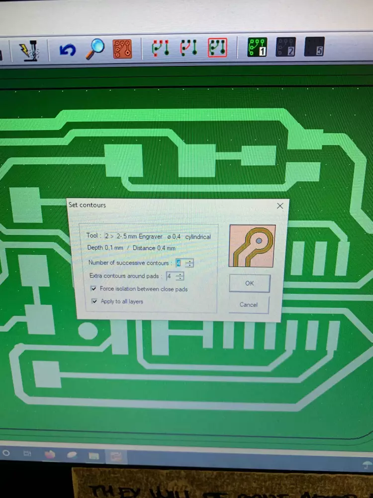
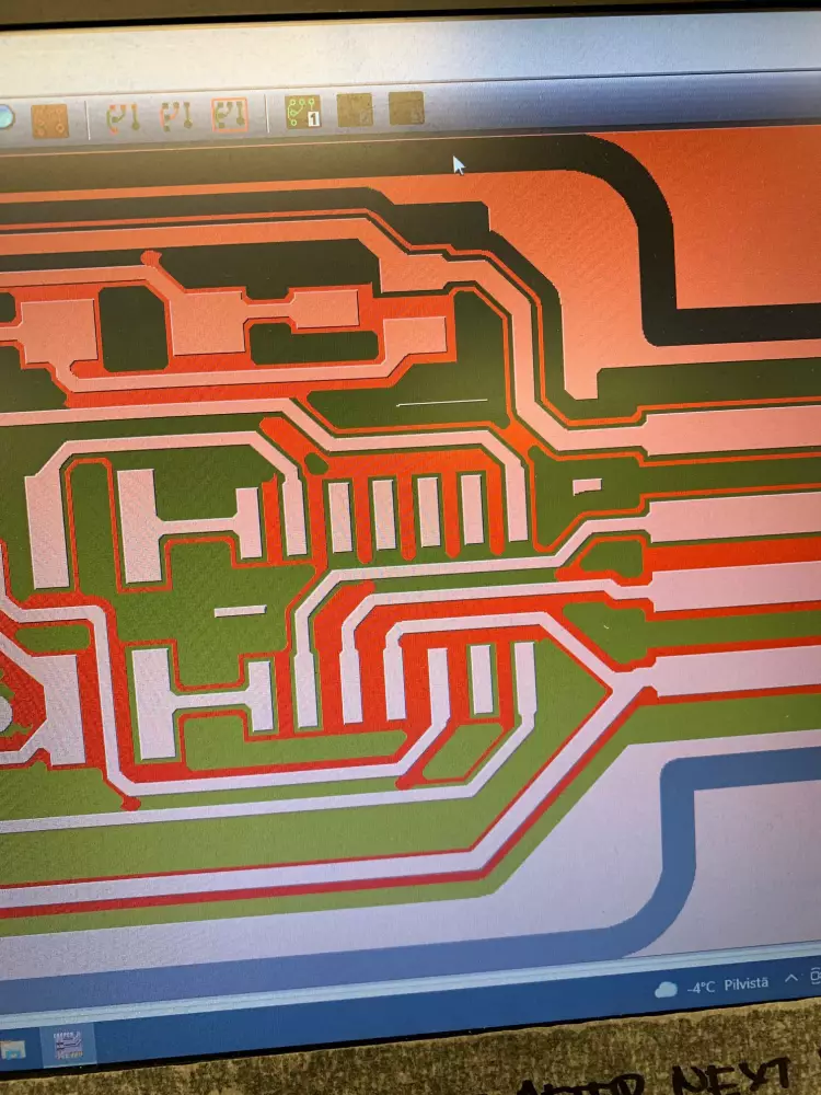
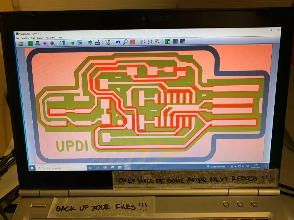
Next up we can check how the engraving result looks. We click on the Set contours -button, and set the Successive contours as well as Ease contour around pads to 4. 4 is typically a good setting for milling pcbs.
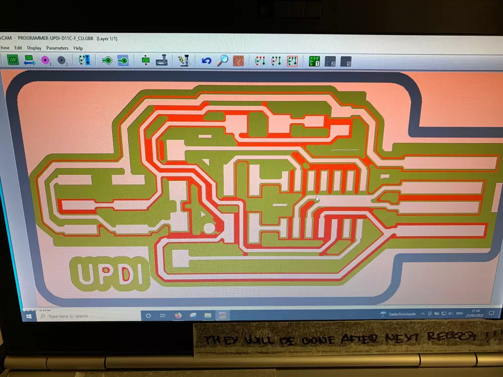
We can see that the two tracks are connected with each other in the end result. To fix this, switch back to the non-contour view, select each track individiually, right click, and select Change width of that track and change width to .38mm for both of the tracks. Now if you regenerate
contours, the issue should be fixed.
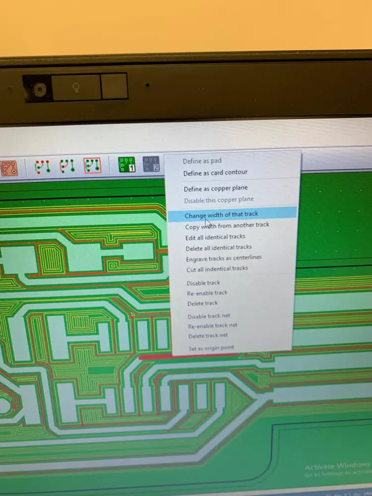
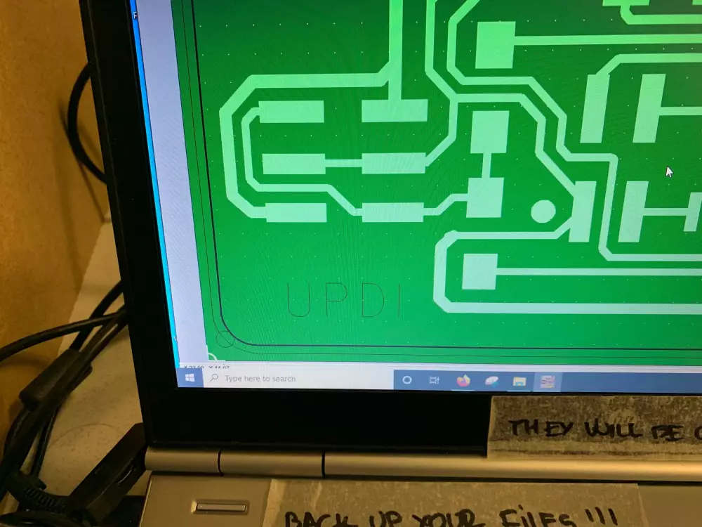
Another thing we need to fix is the engraving of the "UDPI" text. We don't want to engrave around the text, but instead engrave the text as a single line. To do this, go back to the non-contour view, select one of the letters, right click, and choose "Engrave tracks as centerlines". This should change all the letters to 1px lines instead of the thick lines they were before. Now if you regenerate contours again, they should be simple, thin engravings.
With that, we're ready to export the file for milling. Select the "Mill"-button from the menu. Select the engraving and the cutting processes as the ones that should be exported. Before exporting, make sure that the XY Zero is White cross, Z zero point is Circuit surface and that the speeds for both tools are 10mm/s. Now if you click OK, two .egx files will be generated, one for the engraving process and one for the cutting process. You can identify them by comparing the tool index (TX) in the file name with the index of the tool in the Tool library. For a quicker methdo, yu can use the file size, which usually is bigger for the engraving file.
Now you can open the control panel for the SRM-20 milling machine, called VPanel for SRM-20.
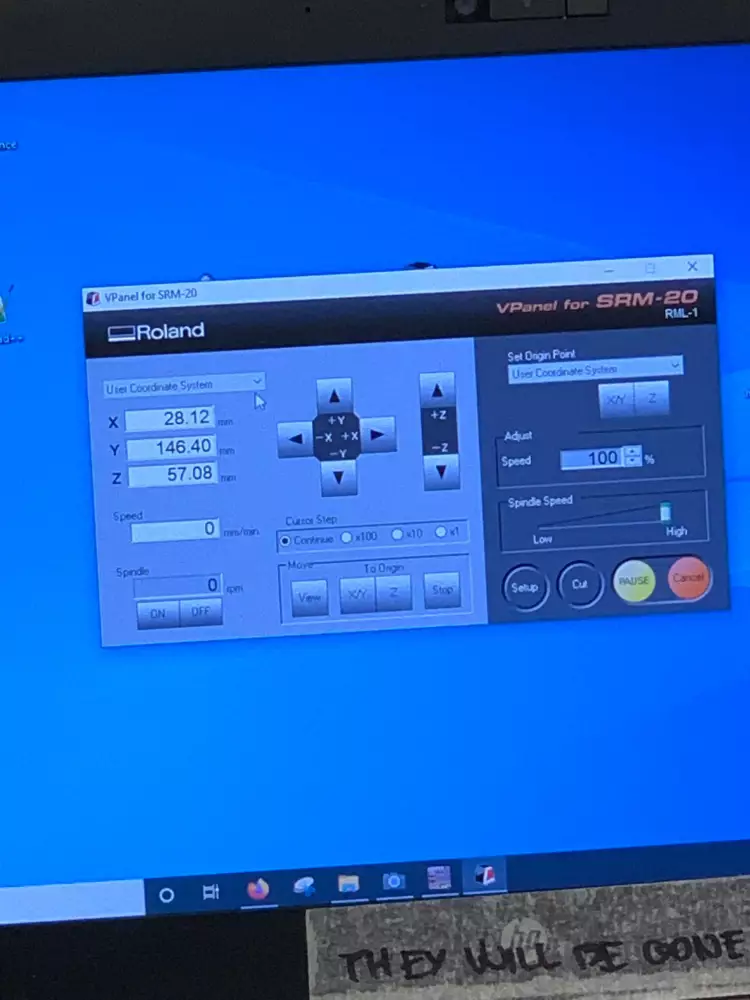
Here, we start by selecting User coordinate system for both the general coordinates and the Origin Point. In Setup make sure to change the command set to RML-1, because that is what CopperCAM spits out.
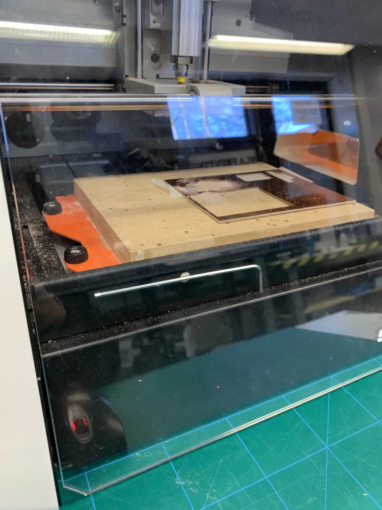
At this point it's a good idea to install the copper plate that we are going to milling on the bed. Move the bit out of the way by using the arrows in the VPanel software. To do this faster, make sure the Cursor Step is set to Continuous, this way you can move the milling head freely without steps.
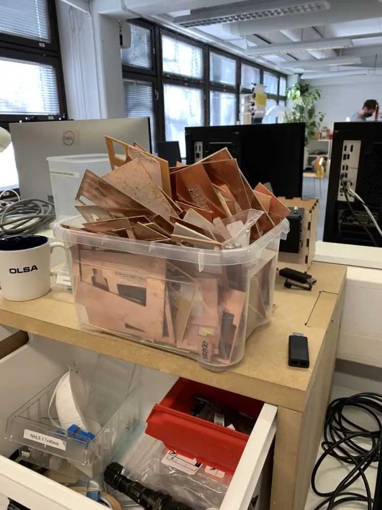
Next, take a FR1 plate from the scrap pile, and remove any possible tape traces from it.
After this, apply a new tape, and attach it to the bed to a relatively flat spot on the surface. If the bed is too far back, use the "View" button on the lower part of the VPanel software to move it forward. Also, be sure to brush any debris out of the bed before attaching. I found out that the brush is quite messy and can also add debris, so be sure to clean it on something before using. Like Bob Ross said, "Beat the devil out of it".
At this point, you can also install the engraving bit. We're going to be using the .20-.50mm bit. To install it, make sure the hex nut on the milling head is loose, insert the bit all the way until the colored collar touches the head, and tighten it using the the hex nut. Not a lot of torque is needed, but make sure it's tight. Also be careful, the tip of the bit is really sharp.
After this, we can set the Z origin. Move the bit over the copper plate using the Continuous mode. After this, switch the step to x100 (1mm), and move the milling head down on the Z axis until there is about a fingers width of space left on the piston/rail/whatever the milling head moves on.
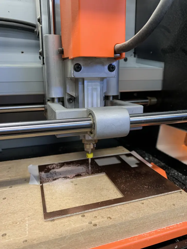
After this, loosen the bit, and let it touch the surface. Make sure you let it down gently. After this, tighten the bit again.
Now, in the right side of the VPanel, click the Z button under "Set Origin Point", and confirm. Now your Z coordinate should show as 0.
To set the XY origin in the similar fashion, lift the bit up using the arrows in VPanel, move the bit to the bottom left corner of the area you inted to cut on, and press the XY button under "Set Origin Point".
Now we are ready to mill. Close the lid of the machine and press the "Cut" button. A dialog should appear.
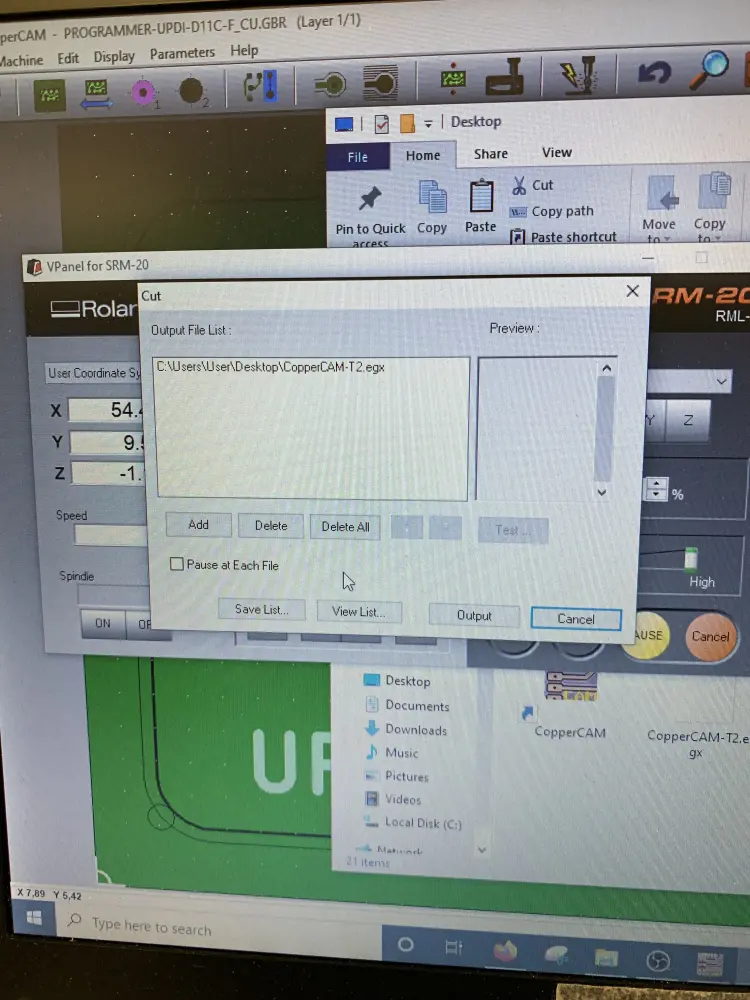
Press "Delete all" to delete previous jobs, and use the Add to locate and add your engraving job to the list. After this hit "Output".
The machine should now spin up. You will see an error about the RML-1 command set, just click "Resume" here. Lower the speed in VPanel to 50% at first to see if the job seems to be starting out correctly. If everything looks good, you can increase the speed to 100%.
After your engraving has finished, check that all the copper material was removed from the engraved bits. If you need to do another pass, lower Z in VPanel by X1 (0,01mm). You need to be able to slide a paper underneath. The bitshould leave a mark on the paper, but not get stuck.
After you've engraved successfully, you need to change the bit to the cutting bit. After changing, reset the Z origin using the same process as for the engraving bit. You don't need to change the XY origin. After changing the bit, remove the engraving job and add the cutting job the same way you did when adding the engraving job.
After the board has been cut out, vacuum the removed material using the hand vacuum that should be somewhere under the desk.
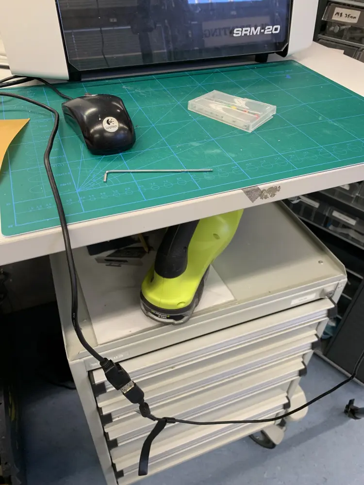
Press the "View" button in VPanel to bring the bed to front, and use the butter knife looking knife to pry out the board.
After this, the PCB is done. Remove the bit from the milling machine, place the hex wrench on the magnet under the lid, and clean up all debris from the table.
Soldering
Board prep
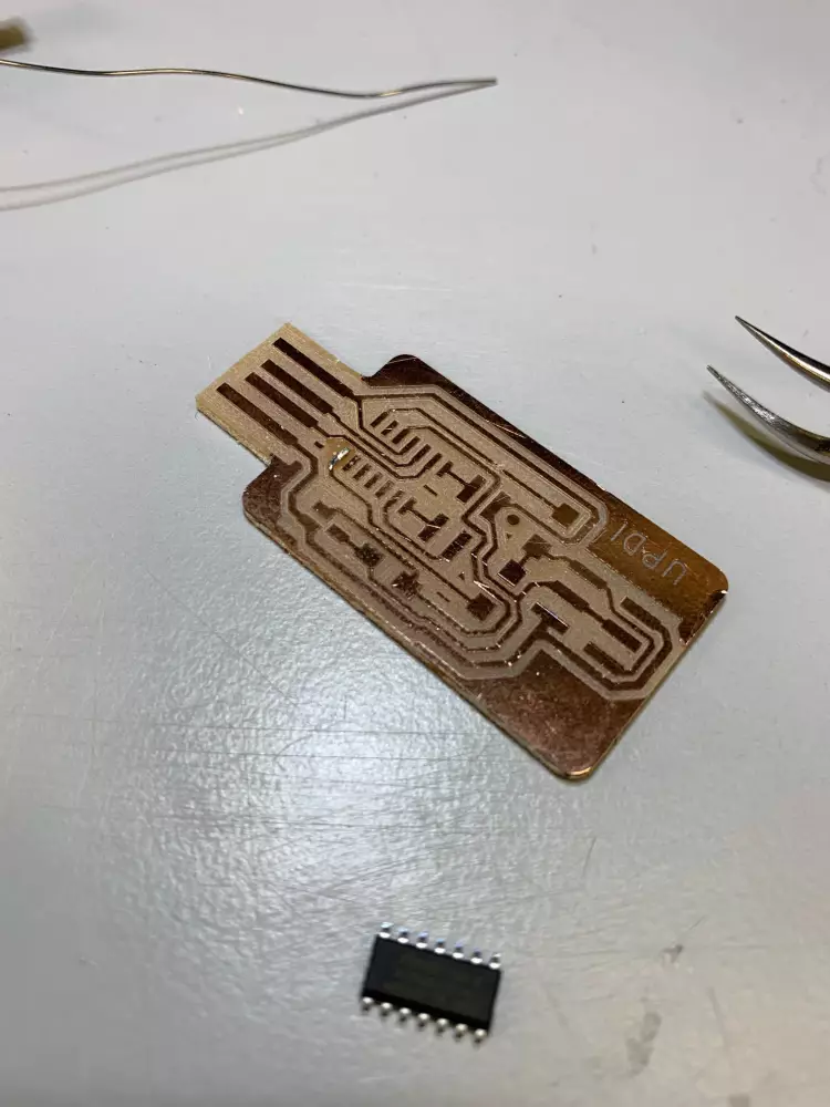
Now we can move on to the soldering part. To start off, use the multimeter to check that no two traces on the PCB you milled are connected. You don't really need to check every trace, but just spots that visually seem tight or otherwise look like they might be connected.
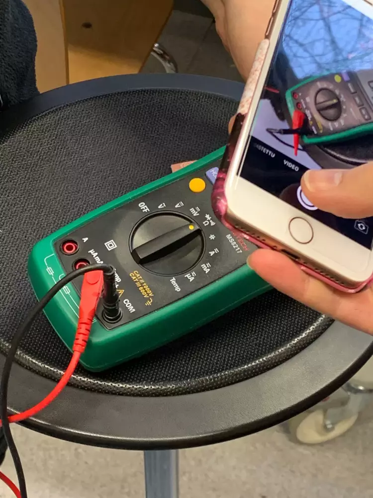
To do this, use the connectivity mode on the multimeter, usually marked by Ω, the symbol for ohm. Pressing the yellow button on the multimeter a few times should make a symbol resembling a sideways wifi symbol appear on the screen. This means that when the circuit is closed, the multimeter beeps. You can check this by touching the two tips of the multimeter together.
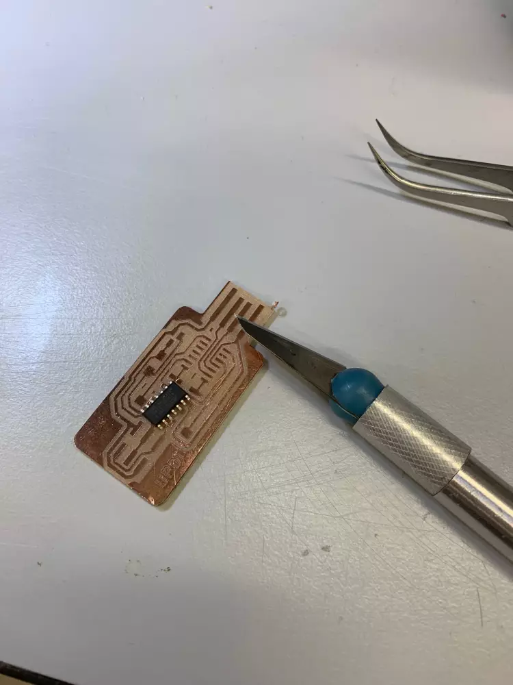
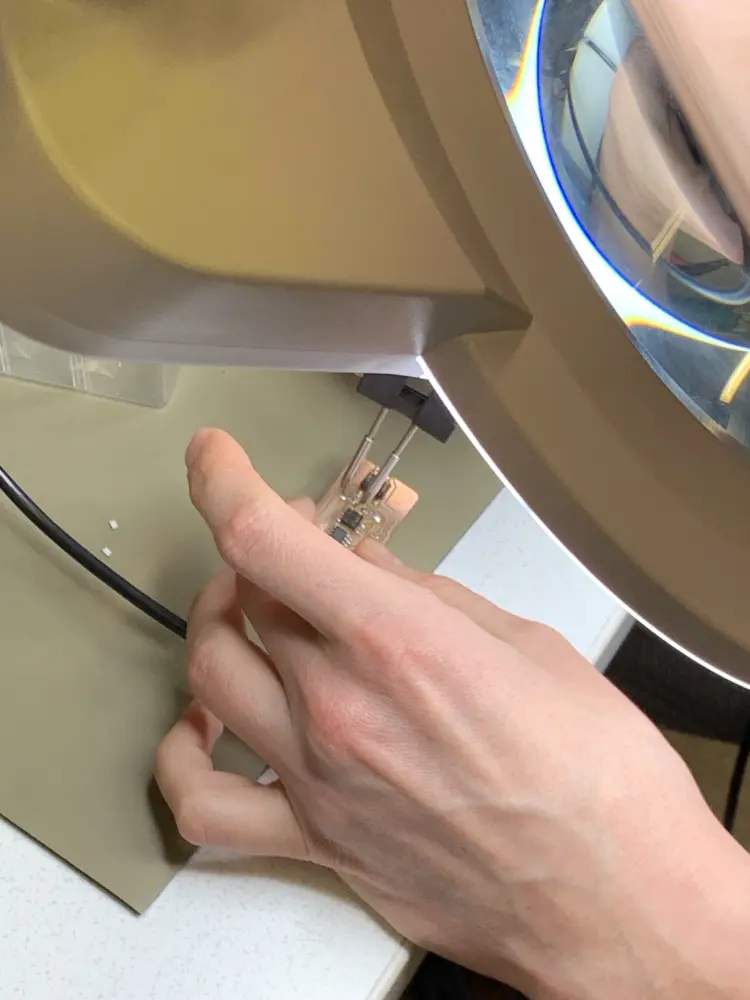
If you encounter any spots that are connected, you can gently scrape away connecting material with a knife. You can either use the camera connected to a screen or the big magnification glass to work with precision. You also need to scrape the excess copper off from the USB connector.
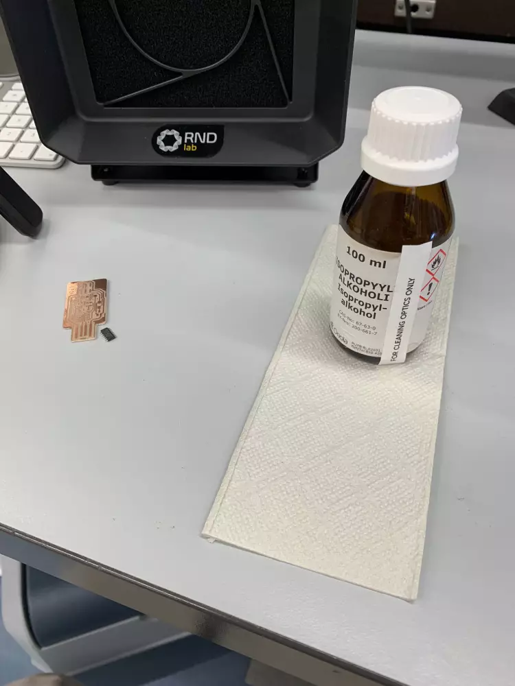
After scraping the excess copper material off, clean the board with a paper towel dampened with isopropyl alcohol. You can find the IPA in a cooler under one of the tables.
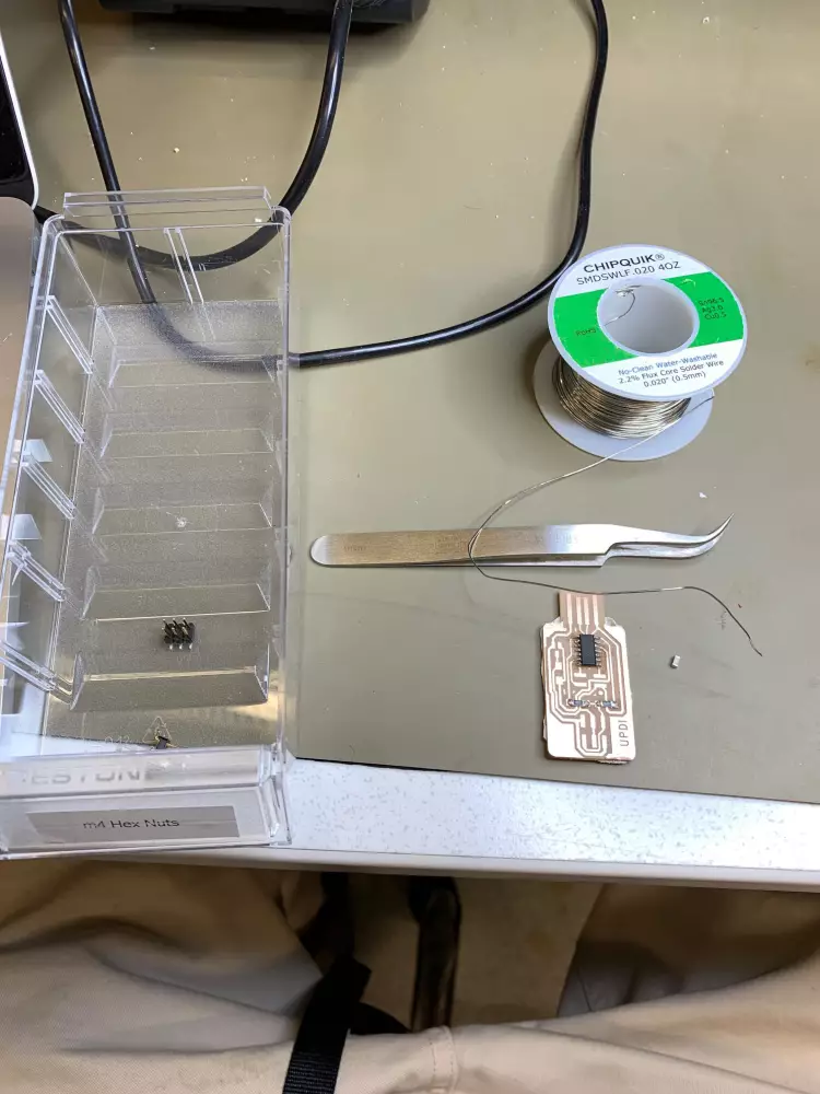
Collecting components
After the board has been prepared for soldering, it's time to gather the components for us to solder. Pick up one of the empty plastic drawers in front of the component shelves. Into this box, gather the following:
- The MCU
- Resistors
- Cap
- Stuff
This way you don't need to take the whole component drawer to your workspace and thus hoard all the components to yourself.
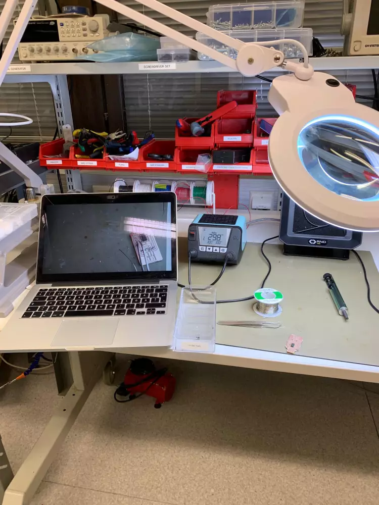
Actually soldering
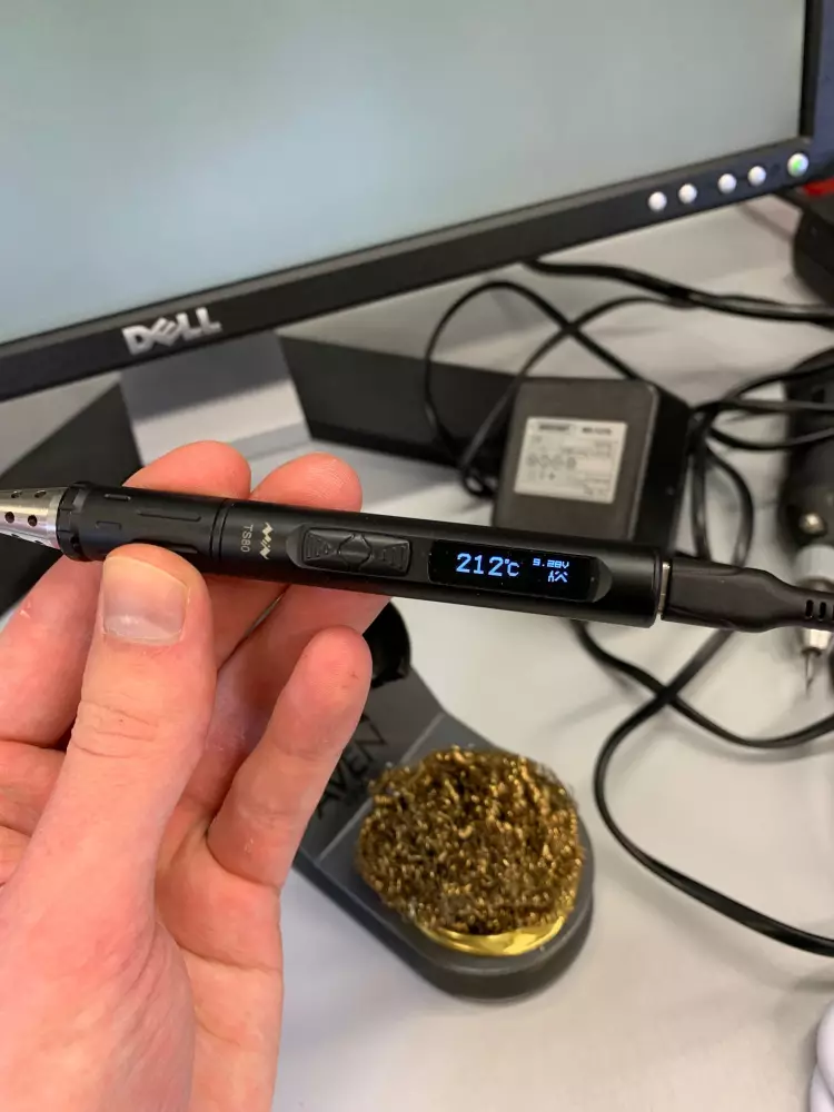
For most of my process, I used the TS80 portable soldering iron. After using it against one of the dedicated weller machines, it definitely didn't feel as easy to solder with, but that might also be due to it having a pointed tip instead of a chisel tip, which seemed to be easier to get under surface-mount components. As for the soldering temperature, I hovered around 280 degrees Celsius.
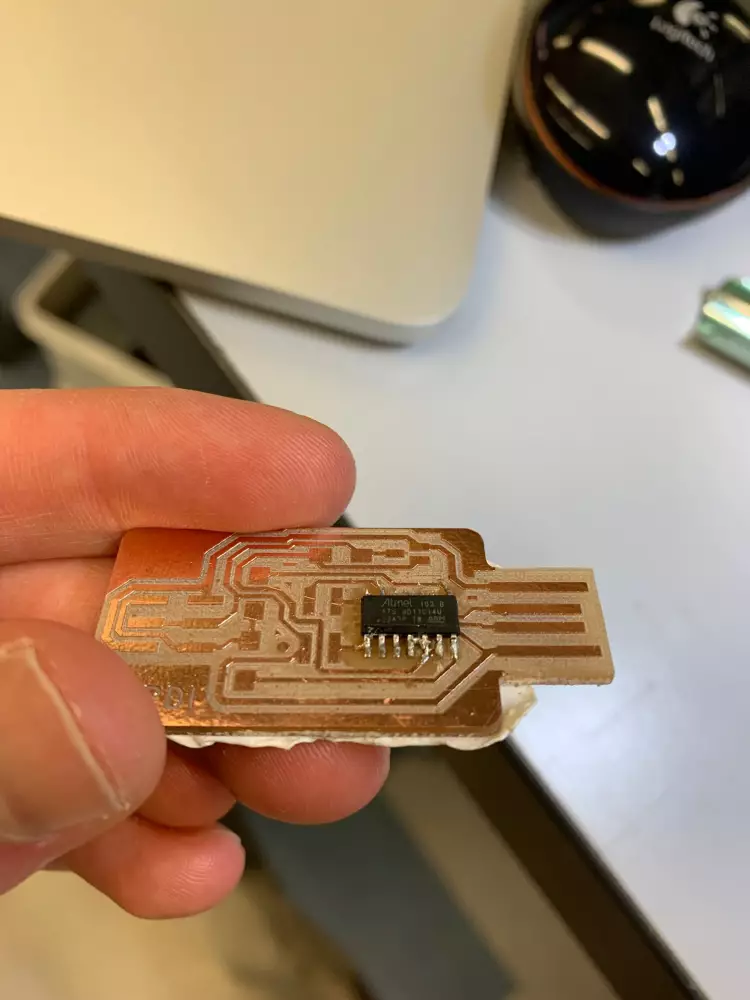
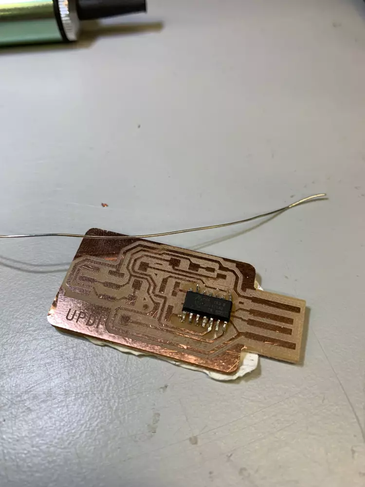
To start off, pick up the microcontroller (MCU), and place it on the PCB. One of the edges on the MCU is beveled. This bevel should be on the right side of the MCU when the USB is facing you. Below is an example of incorrect orientation.
After you've aligned the MCU correctly, move it to the side for a bit. Melt some solder on one of the corner pads. After this, let it cool down a bit, and place the MCU on top of the pads. Pressing down on the microcontroller with either pliers or your finger, try to get the soldering iron between the leg of the microcontroller and the pad with the solder on it, melting the solder and thus fixing the component in place.
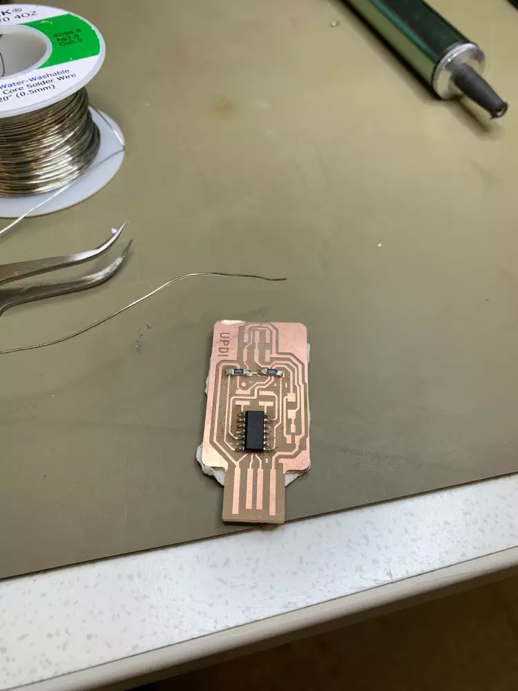
After the first leg, you start soldering from the opposite corner. Try to get the soldering iron between the MCU leg and the copper pad, and after heating for a few seconds, stick some solder on the iron, melting it between the pad and the leg. Repeat this step for all the legs, and your microcontroller should now be soldered on.
With the MCU, I managed to solder together a few legs. To fix this, I used the solder sucker. I heated up the blob of solder connecting the two legs, and after the solder melted, I used the solder sucker to suck it out. This usually takes a few tries, and you have to try and keep the heat on the solder while using the solder sucker for it to actually work. Takes a bit of practice, but eventually I succeeded.
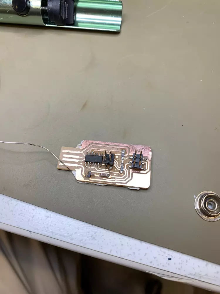
After this I followed along the video tutorial, first soldering the resistors, then the capacitator, then the voltage regulator and lastly the headers. With the 2x2 header I managed to lift up one of the copper pads while fiddling around with it, but managed to get a connection with only solder.
Programming the programmer
To get the PCB working, you first have to install a bootloader on to the board. This requires another programmer and a bootloader binary.
The bootloader binaries can be found here under bootloaders/zero/binaries. For this chip, the right binary is sam_ba_SAMD11C14A.bin. The repo also has instructions how to add it as a board source for Arduino IDE.
To actually program the board, you can either use the edbg program from the command line, or use the Arduino IDE.
Trial and error
Upon finishing the board, I asked Kris to program it. He demonstrated me the process using the edbg binary from the command line.
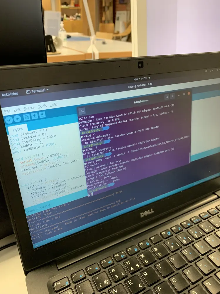
When trying to upload the bootloader, the upload failed. We tried it a few times, until Kris pointed out that the MCU was actually soldered on the wrong way around.
To fix this, you need to desolder it. The easiest way to do this is to use a heat gun while gently pulling the MCU up with pliers. This way you will pull the board out once the solder melts from the heat.
After desoldering, you need to clean the leftover solder from the copper pads with some solder wick. Place a clean part of the wick on the solder you want to remove and apply pressure gently with a soldering iron. Once you see the fumes of the solder melting, lift the wick along with the soldering iron. Be careful to lift the wick first, otherwise you can solder the wick into the pad, which happened to me a few times, and can easily result in you lifting up the whole copper pad, which also happened to me a few times.
After soldering on the MCU the right way, the upload still failed. This probably means that the microcontroller was destroyed by the heat at some point, so we decided to replace it with a new one.
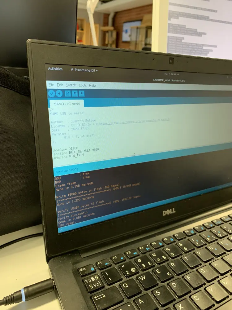
After this the board worked partially. The bootloader installed correctly, but the board still wouldn't successfully upload code to another board. I did some debugging with a multimeter to see if I could find any shorts or cold joints, but nothing seemed to be out of order. I reheated every pin in order to create a better connection between the components, but still nothing.
This is the part I personnally find the most frustrating about electronics, the complete lack of feedback for possible errors. At this point, we decided that the best solution would be to mill and solder another board completely.
Luckily, the milling process was faster the second time around, as my files were ready on the computer and I already had gone through the process once. Soldering also proved to be easier this time around, with only a slight hiccup happening.
I somehow managed to form a connection with the both ends of both resistors, so I desoldered them using the heat gun and pliers. Kris later showed me that this can be done even more easily using the soldering pliers that can be found at one of the workstations at Fab Lab Aalto.
When picking new resistors, I accidentally picked 4.99M resistors instead of 4.99k, which resulted in the same behaviour as the previous board: the bootloader would upload successfully, but uploading code to another board failed. Kris spotted this, desoldered and soldered on the right resistors. After this I successfully managed to program another board with the programmer. Yay!