Final project
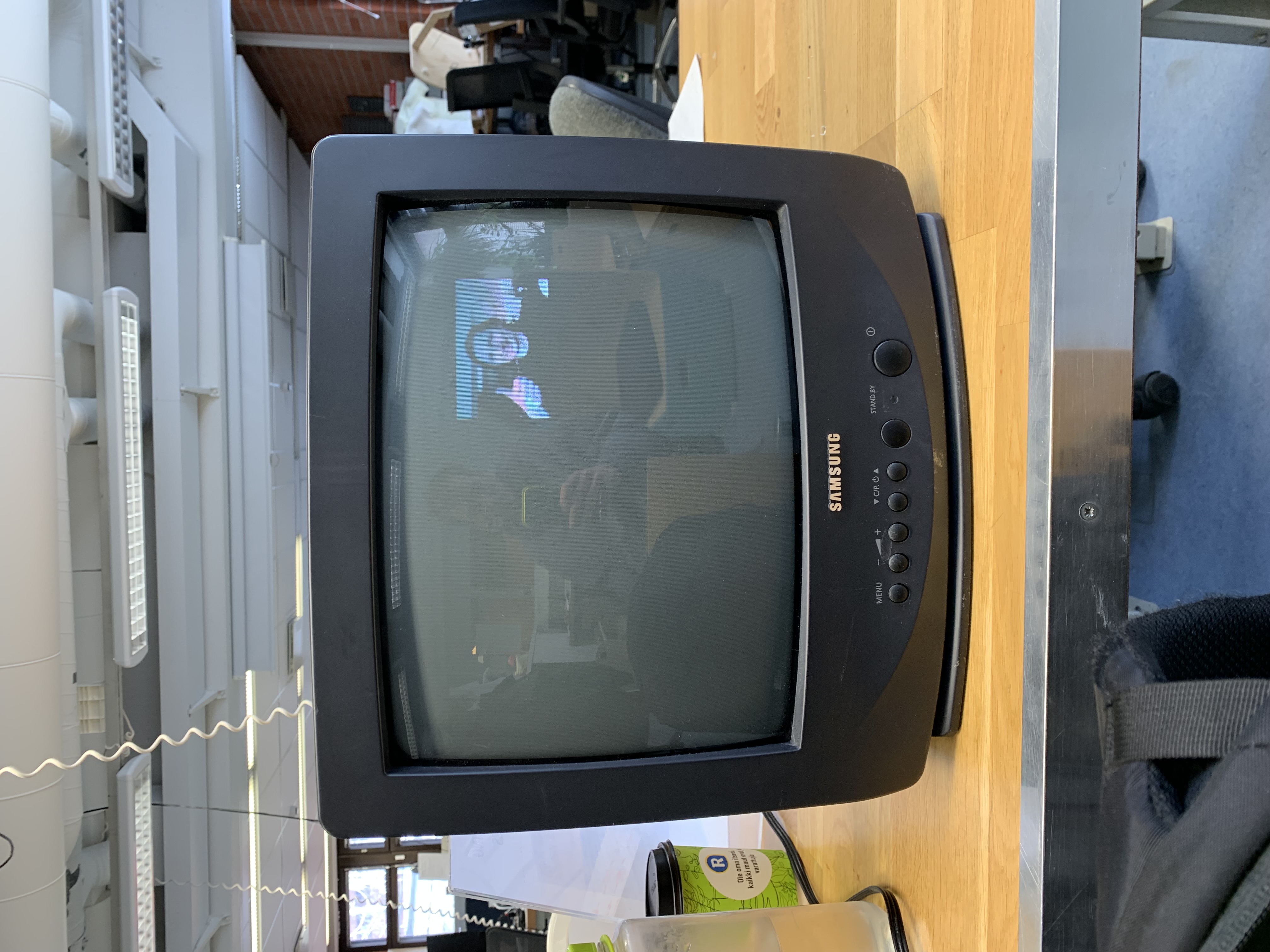
For my final project, I'd like to do a pirate TV station. The idea would be to have a small chip, where the user could plug in a usb drive containing the media to be broadcast and the chip would broadcast it in a small, say 1-meter radius to a nearby CRT TV tuned into channel that I still need to decide after researching the frequencies of different analog TV channels in Finland.
Heavily inspired by this project. Check this link later when it works.
Useful resources:
- https://hackaday.com/2020/08/26/driving-a-pal-tv-over-rf-thanks-to-pwm-harmonics/
- https://www.youtube.com/watch?v=8sQF_K9MqpA
- Theres also this PDF I found laying around on a hard drive of mine. No Idea who is the original author, but all credit goes to them.
Final Result
Visual inspiration/Enclosure design
For visual inspiration I've put up a are.na board here. I'm very much inspired by transparent acrylic encasings, where the pcb would be visible. On the contrary, I'd like to use as little material as possible, and even then, I'd like to use waste material. Sustainable but beautiful, which might prove to be difficult
As for the design of the PCB itself, the antenna needs to be exposed from the enclosure, and if possible, I'd like add a small screen for the user to see what is happening.
Progress
March 9th, 2022
I checked out this video about sending out NTSC video from an ATTiny chip. In it the author describes a resistor network that can be used as a DAC for sending out various voltages from a digital pin.
I talked about it with Kris, and discovered that the ATtiny412 already has a DAC pin. This should be enough for transmitting monochrome PAL video.
My next steps are to actually figure out how PAL works. Here are some links to get started.
I could also use a library such as arduino-tvout to maybe bypass the learning and test that transmission to TV even works from the ATtiny412. Regardless, it's probably a good idea to do some research into the source codes of these libraries (which requires reading up on PAL). Other libraries to check out are this and this (uses PWM harmonics)
Generating an analog video signal
To understand how we can output analog video, we first need to understand what a signal is. To put it simply, a signal is data encoded by varying a voltage over time. There can only be a single voltage during a single moment of time, but this voltage can vary slowly, or very quickly, resulting in different waveforms. Video data encoded into a signal in this manner is often called baseband video. The baseband video signal gets transmitted to a TV either by cable or via the air, parsed, and then displayed. But how does the TV know what to do with the signal? Enter PAL
PAL
PAL, or Phase Alternating Line, is a standard used in most of European countries to encode video data into a analog signal. The video signal in PAL is split into frames, frame being a single image to display on the screen. A frame is then further split into scanlines. A scanline describes a single line of the frame, or the image being drawn. In PAL, these scanlines are grouped into two fields, one for even lines, and the other for odd lines. When a frame is transmitted, first all the even lines get sent, and then all the odd lines get send, after which they are interlaced to form a whole image.
Horizontal blanking
A scanline starts with a horizontal blanking period:
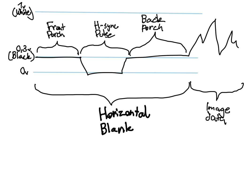
This blanking period lasts for about 12.05µs, and is divided into three sections: Front porch (1,65µs), H-Sync pulse (4,7µs) and Back porch (5,7µs). Apparently most microcontroller video outputs seem to use a H-Sync pulse of 4µs and it should work fine. After the blanking period comes the image data, lasting for total of 51,95µs, until a new blanking period follows, starting a new scanline.
Interlacing
As mentioned above, a frame consists of two fields, one for even lines and other for odds:
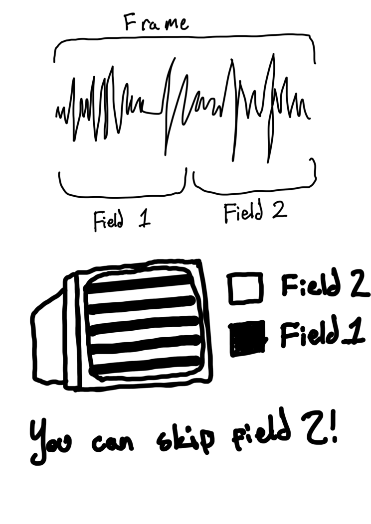
These fields get interlaced to form a whole picture. Apparently you can skip the second field by some hacking, which is easier than interlacing.
Transmission of video over radio
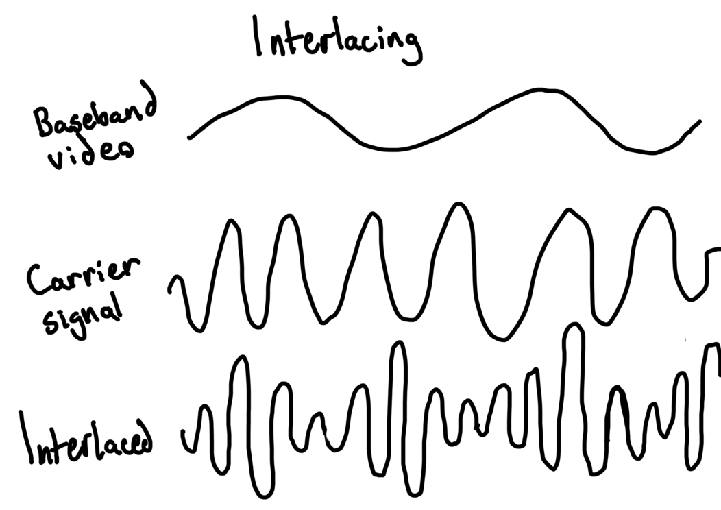
To transmit the baseband video signal, it needs to be modulated into a carrier signal, which depends on on the TV channel we're going to broadcast to. This means that the signals are combined so that carrier signal gets louder in the points the baseband gets louder. Below is a pretty bad diagram of this:
ATtiny412 dev board
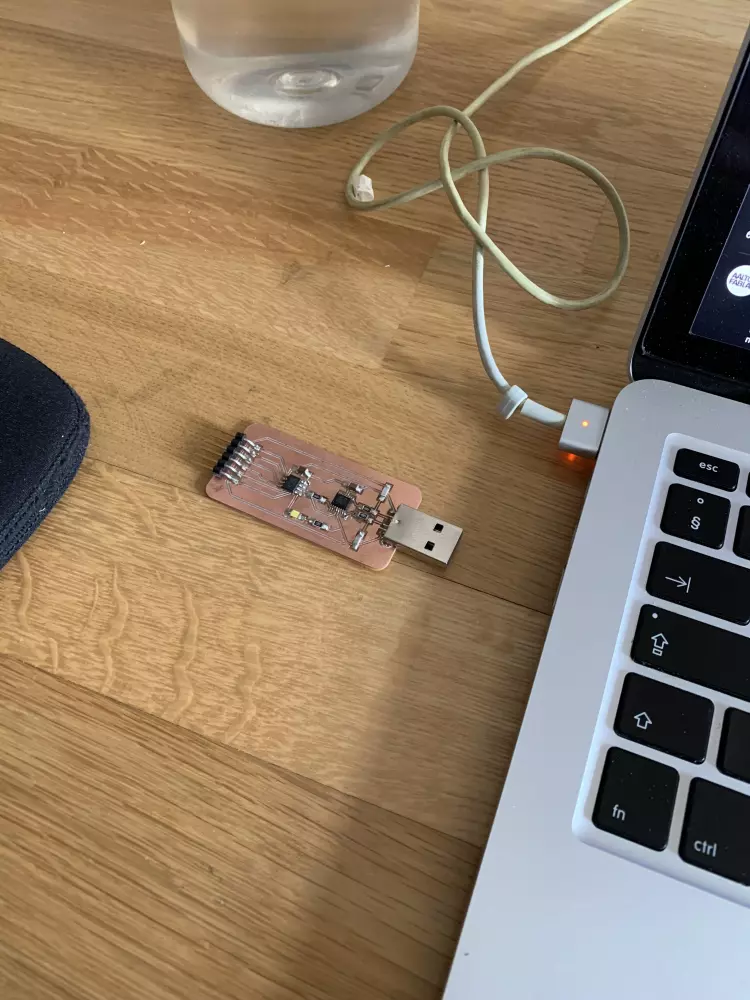
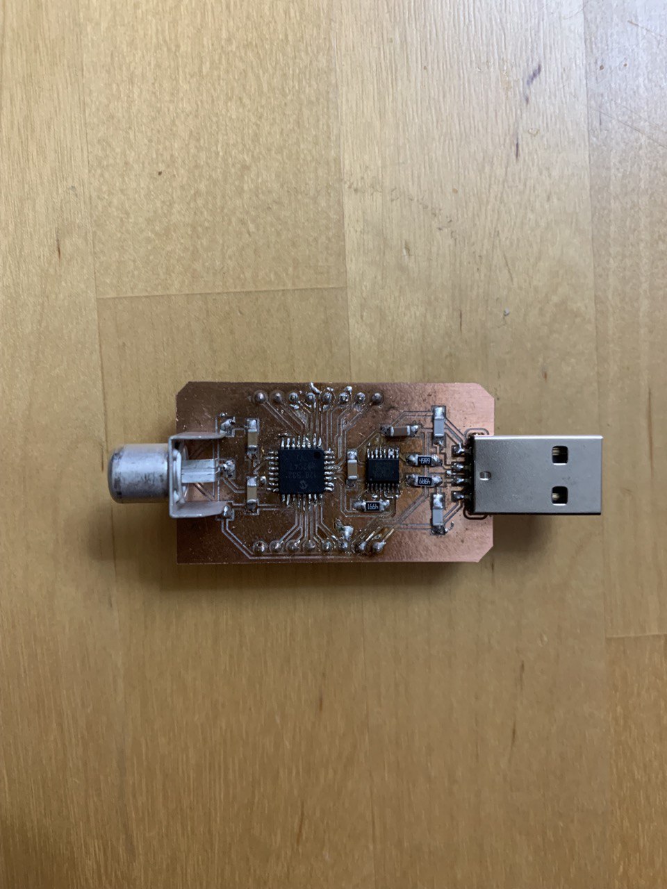
To test outputting PAL signals, I designed a simple ATtiny412 development board that could be programmed through USB thanks to the FT230X chip, which is really small and a pain in the ass to solder. I designed the development board to also have headers for the DAC and Power pins for easier connectivity.
After this I read up on PAL timings, and programmed the MCU to generate a PAL signal through the DAC pin. More detail on the code can be found on the assignment page for the Output Devices -week.
Trying to display an actual Image
After generating a demo image of half black half white, it was time to try and generate a PAL signal from a real image.
Image to header
The first step was to generate a C header file that contains all the pixel data of a grayscale image. In retrospect, I realize that this is already where I kinda went wrong. I used both GIMP and ImageMagick to generate a .h file, but both generate a array with pixel values (in random bit-depths no less), while in reality I need an array with luminosity values between 0.3V - 1V (in a 8 bit integer of course). I'll need to program a script in Python to do this for me, but it really shouldn't be too big of a problem.
Timings
The second issue that arises from trying to display a image through PAL are the pixel timings. As the active display area (the actual image data) lasts for about 51.25µs, one needs to calculate how long one pixel of the image should take to draw. As we are going into nanosecodn accuracy here, it really gets tricky. I did a good amount of researching timers on the ATtiny412 only to be super confused of their actual accuracy and how to use them.
One way to solve this issue seems to be convert all PAL timings to CPU cycles, and use the internal counter to time things using interrupts. I didn't really have the motivation to delve into the counter part after struggling with timers, so I was pretty demotivated at this point.
STM32
After discussing a bit with Kris, he ended up ordering some STM32 black pills, one of which I could use for developing my project. The STM32 runs at about 100MHz, so it should have more than enough horsepower to generate a PAL signal on time.
DACless life
After getting the STM32 up and running, and uploading some blinky code with PlatformIO, I started looking into how I could output analog signals with it. I found out that the STM32 does not have a built-in DAC (can't remember if Kris mentioned this), so I needed to use a external DAC chip and use I2C to communicate with it. I started wondering if I2C would add needless overhead (probably not), and in general I was not feeling like milling another board, so I decided to do some research into boards that would have fast enough clockspeed and built-in DACS.
ESP32/ESP8266
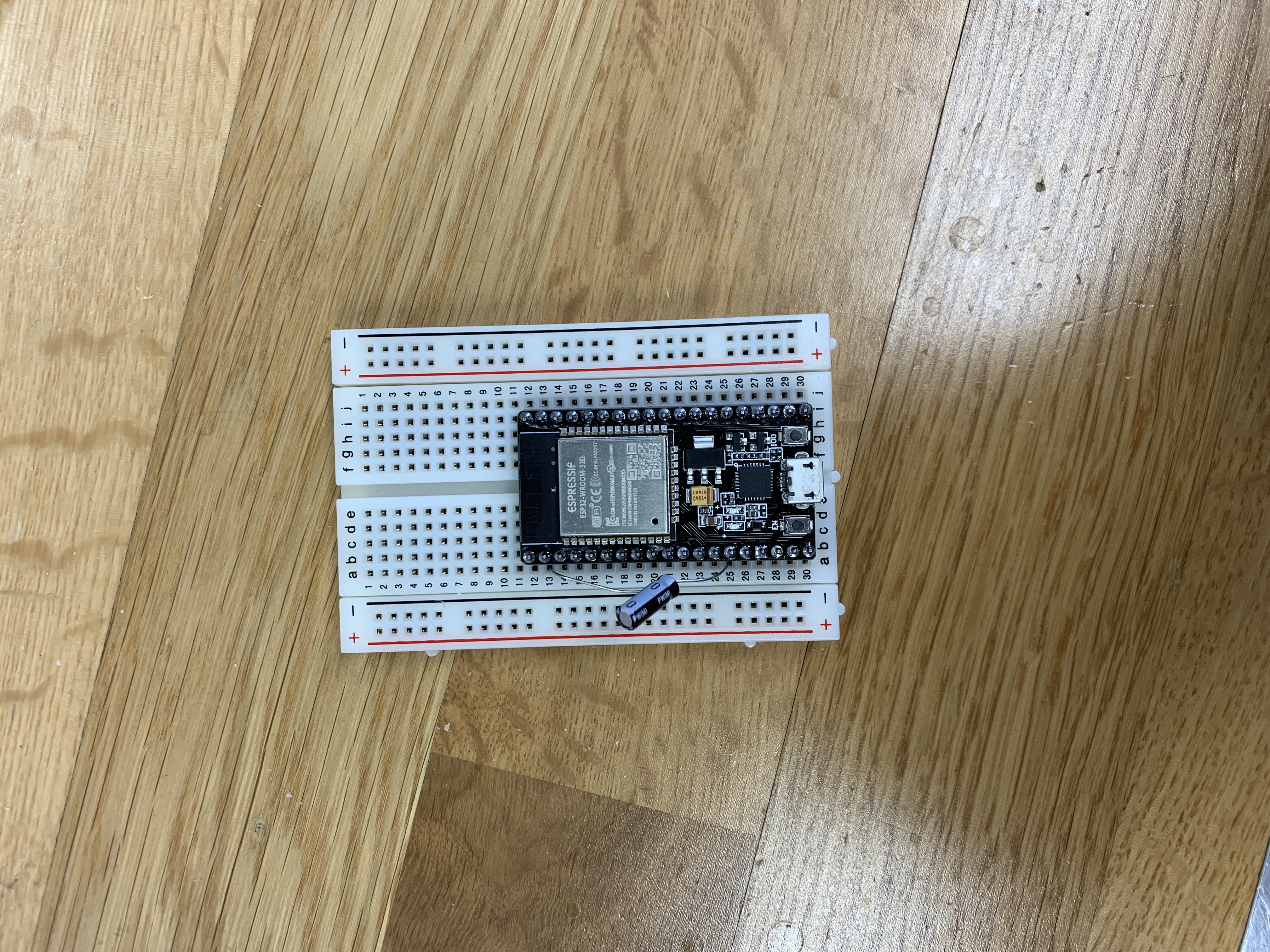
After a bit of googling around, I found a ton of composite video projects for the ESP32/8266 MCUs. The 8266 doesn't have a onboard DAC though, so I decided to pick up a ESP32 development board from Uraltone, as it was only 15e and I live really close to Uraltone.
Diving deeper into the ESP32 programming.
To program the ESP32 development board, I used PlatformIO. Installing the libraries was more or less automatic, and I could get a blink code compiled fairly quickly. Programming it on the board proved to be harder though. Turns out you have to hold and release the reset button when uploading code. On my board this seems to work completely arbitrarily though, and I've yet to figure out how to press the button to make it consistent. Adding a capacitor between EN and GND pins should solve this though, so I need to try that next.
Displaying PAL video
With some code running, I decided to port over my previous PAL code to the ESP32. Everything went more or less smoothly, as the ESP32 documentation for using the DAC is pretty good. With the code uploaded and running, I tried to plug it into my TV, aand all I could get is a rolling and flickering image.
After a bit of debugging, it turns out that the Arduino function delayMicroseconds only accepts integers, and thus ignores all fractions I passed to it, screwing up both vertical and horizontal sync timings. Back to the drawing board it was.
I2S + DMA
After researching existing projects for the ESP32, it seemed that a lot of them were using something called I2S in combination with DMA. Turns out that I2S is a protocol originally made for transfering audio signals. It uses three lines:
- Serial data line: Where actual signal data travels
- Bit clock line: Tells the I2S peripheral when there is a new bit to read
- Channel select line: Also known as the word select line. Tells the I2S peripheral when there is one words worth of data on the line.
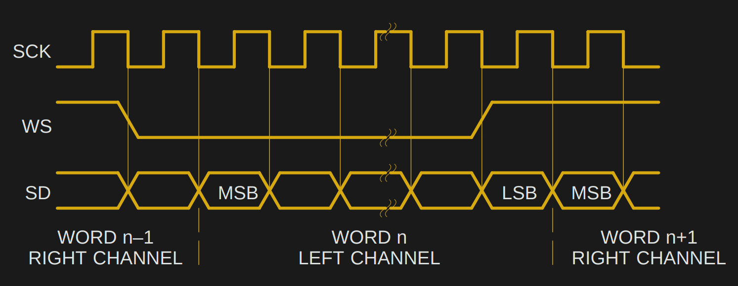
The diagram above shows the timing for I2S lines. Image courtesy of Hackaday. There are a few different standards for transmitting data, mostly having to do whether data is sent on the first pulse of the bit clock or second. The image shows the Philips standard, where data is sent on the second pulse.
The benefit of I2S is that it is really fast in transmitting data, especially with a fast microcontroller like the ESP32. It's also a fairly loose spec, so that it can be used to transform arbitrary waveforms, not just sound.
Combined with DMA (Direct Memory Access), we can read image data direct from memory and output using I2S, bypassing the CPU completely.
Timing using the I2S
However, while many projects mention that they use I2S to transmit PAL data, none of them explain how they actually use to I2S to time the signals. I've seen the term PDM being thrown around, and while the ESP32 I2S module has PDM capabilites, no projects seem to actually use it.
I've come to the conclusion that the timing of the signal happens with the word select line, as it's what determines the sample outputrate of the I2S. When you know the rate of the sample output rate, you can count roughly how many samples are output for each part of the PAL signal, and time them by padding out the data.
Modifying code
To try out if PAL output even works, I grabbed bitluni's CompositeVideoSimple from GitHub to try out. I simplified the code so that it only outputs a image, and sure enough, it works.
However, the code is way too overcomplicated for my needs, so recently I've just been spending time trying to simplify it. Stripping down the graphics part was really quite easy, but the actual part that interests me, i.e. the composite output is really complicated, as it uses interlaced video and pretty peculiar timings for syncing. It also has magic numbers everywhere. But, I'm getting closer to understanding it, so pretty soon I should be able to roll out my own.
Back to ATtiny
After spending some time with the ESP32, and trying to debug how to actually time signals with I2S (the documentation is really pretty bad) I gave up. No matter how much I tried to decipher the code, I just couldn't make sense of it. I will probably try to return to it some day, but it will have to wait.
I decided to go back to the ATtiny412 and try to use timers instead, as this way I wouldn't have to worry about delaying exactly the right amount to achieve correct scanline timing. I could just do whatever in the timer interrupt, and it would fire with the correct timing. There's this pretty handy document with code examples that shows how to configure TCA to generate interrupts on a ATtiny. The main thing to understand here is how the interval of interrupts is determined. In this case, there's two things:
Firstly, the timer period, or the PER register. This determines the amount of clock ticks it should take until we fire an interrupt. But what is a clock tick? This gets us to our second point: how the clock is determined. On the ATtiny412, the clock frequency is CLK_PER divided by the clock prescaler value. I wanted the clock to be fast as possible on the ATtiny, so first we need to set the CLK_PER to its maximum value of 20 MHz:
  // Disable Prescaler
_PROTECTED_WRITE(CLKCTRL.MCLKCTRLB, 0); // set to 20Mhz (assuming fuse 0x02 is set to 2)
This disables the scaling of the main clock, and thus CLK_PER is whatever the CPU frequency is (either 16Mhz or 20Mhz).
After this, we set the prescaler value of TCA to 1, so that the clock frequency is 20 Mhz.
// Divide clock by 1, enable counter
TCA0.SINGLE.CTRLA = TCA_SINGLE_CLKSEL_DIV1_gc | TCA_SINGLE_ENABLE_bm;
Now we can determine the clock period. On a 20 MHz timer, one tick takes 1/20 µs. Thus, to trigger an interrupt every scanline (64 µs), we get the following formula:
1/20 * x = 64
Which gives us:
x = 64 * 20 = 1280
Thus, CLK_PER should be 1280. To set this, we do the following:
// Count until 1280 (64µs on 20Mhz)
TCA0.SINGLE.PER = 1280;
Now we have interrupts triggering on every scanline. Now we can place our drawing logic inside the interrupt routine, and not worry about the scanline timings though. We do, however, still need to worry about both horizontal and vertical sync timings. Even if we trigger a draw every 64µs, we need to ensure that we output the right level at the right time for the right duration. My solution for this was to keep note of which line we are drawing, and output levels accordingly:
int currentLine = 1;

ISR(TCA0_OVF_vect) {
  // Print scanline sync here
  // Somehow need to keep count if it's a VSync line or not.
  if (currentLine == 1 || currentLine == 2) {
    longSync();
    longSync();
  } else if  (currentLine == 3) {
    longSync();
    shortSync();
  } else if (currentLine == 4 || currentLine == 5 || currentLine == 310 || currentLine == 311 || currentLine == 312) {
    shortSync();
    shortSync();
  } else {
    horizontal_blank();
    // draw stuff here
  }
  currentLine++;

  if (currentLine > 312) {
    currentLine = 0;
  }
  TCA0.SINGLE.INTFLAGS = TCA_SINGLE_OVF_bm;
}
If you're curious about the shortSync and longSync functions, I go more in-depth here. If you're wondering what the line
TCA0.SINGLE.INTFLAGS = TCA_SINGLE_OVF_bm;
does: it clears the interrupt flag, which tells the MCU whether and interrupt is currently occuring or not.
I added some basic drawing code, and plugged in the board to my TV, and sure enough, it worked! Unfortunately I don't have a photo of this, you'll just have to believe me.
Trying to draw a picture
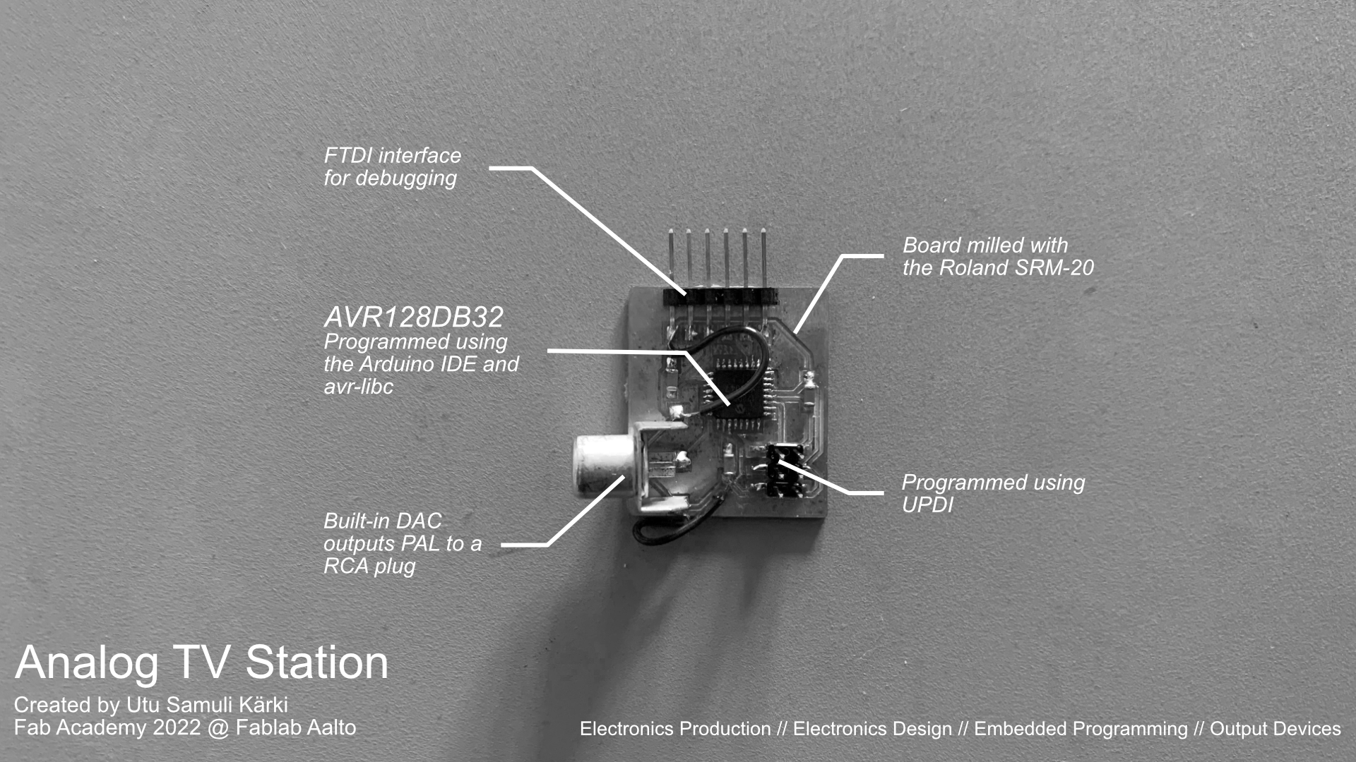
This is where I started tripping up. I wanted to draw a simple greyscale image, encoded into a array of luminosity values. However, even with a really small image, the resulting array ends up being too big for the SRAM of the ATtiny412. It was at this point that I transferred over to the beefier brother of the ATtiny, the AVR128DB32.
AVR128DB32
The AVR128DB32 has a whopping 16 KB of SRAM and 128 KB of flash, which is a lot compared to the 256 B and 4 KB on the ATtiny412 respectively. This means that somewhat large images should fit in the SRAM effortlessly.
My first attempt in soldering the AVR128 chip on a board failed miserably. I completely botched everything, connecting most of the pins together and in the process burning the chip. It was pretty late, I was tired and pretty frustrated, but thankfully Matti showed me how to approach soldering chips like these. The trick is to do a sloppy first run, and clean up with the desoldering wick afterwards. What really helped me with the wick was to melt a little bit of solder on top of it, which aided in sucking off the excess solder from the pins.
My first board also contained the FT230XS, which is dreadfully small, which didn't exactly make this solder job any easier.
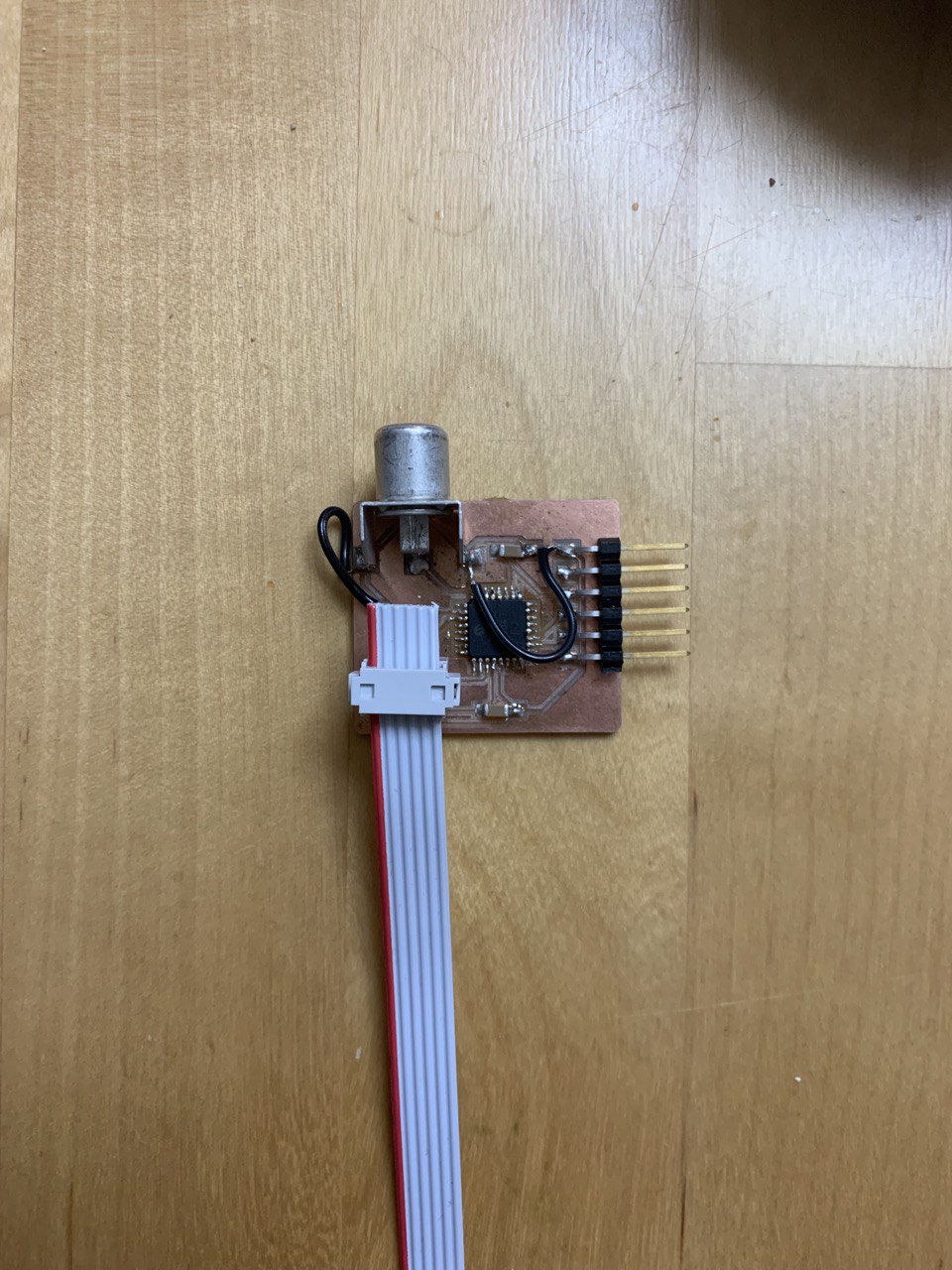
At this point I just wanted a board that works, so for the second iteration I went with a UPDI connector instead of the FT230 chip to speed up the soldering process.
I also added a RCA plug to make it easier to connect the chip to the board. However, as I bent the connector so that it would not touch the surface of the board (I later realized that this was not necessariy, as the outer edge of the board acts as a ground plane anyways) I managed to rip off some connectors, so Matti helped me to jump them with wires.
After a bit of back and forth with the UPDI programmer, we finally managed to upload some code to the board. What a relief.
In hindsight, the FTDI connector turned out to be pretty useless, as using the Arduino Serial library is painfully slow, and doesn't really help debug anything when dealing with microsecond timings. I'm sure it will come in use if I ever need to debug some variables, but even that requires jumping some hoops as I couldn't get the arduino code run in my program when I didn't have setup() and loop() present. One could implement the serial communications with the features of the chip, but I simply don't have the time or patience for it.
Porting the code over to the AVR128DB32 proved to be a bit of a frustrating process. The operation of the DAC and timers is just different enough that at a glance what should be working code does nothing at all. The compiler also doesn't help at all in this stage, as the avr-libc supports multiple chips, and has no idea what chip you are currently using. In the end I managed to work it out, but it required meticulous reading of the datasheets and a few trips to the oscilloscope to debug. I will highlight the main differences from moving to the AVR128 boards from the ATtiny412:
- The DAC is 10-bit instead of 8-bit. This repo helped me a lot when moving my code over
- The AVR128DB32 has something called a high-frequency oscillator, which determines the peripheral clock. This is different from ATtiny where the CPU clock determines the peripheral clock. By default the high frequency oscillator on the AVR128DB32 is set to 16 MHz, but you can change it to be 24 MHz.
- I have a vague recollection that the timer configuration for TCA is different, but I can't seem to find any evidence to back up my claims.
After porting the code over, I had my ATtiny412 code succesfully running on the AVR128DB32:
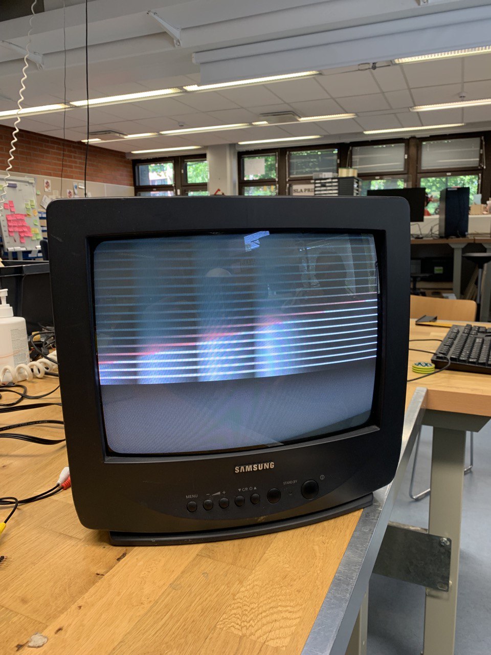
However, even with the AVR128 chip, I was running into issues trying to draw a image. The processor simply wasn't fast enough, and trying to iterate over a line of the image simply resulted in a rolling picture. There are probably some optimizations that could be done, but still it perplexes me. If we have around 52 µs to draw a vertical line, and a single CPU cycle takes around 1/20 µs, we have around 1040 CPU cycles to draw a single line. If we have a image with a horizontal resolution of 100, this means we have 10,4 CPU cycles to draw a pixel. This should be plenty even if we do multiplication and bit shift stuff around when outputting stuff to the DAC.
If I had to guess, the issue is the fact that in the interrupt I iterate over pixels in a for loop. I'm not sure exactly, but this might screw up the timings of the interrupts, as another interrupt cannot occur as long as the interrupt routine is being run. One way to remedy this would be to make sure that each line gets drawn so fast that it's not possible for the drawing of a line to interrupt the timings. This is what I attempted to do next.
Optimization
To try and make the code fast as possible, I opted to only use two colors, black and white. This makes it easy to encode pixel data into bits: 1 is pure white, 0 is black. I wrote a quick script in Python that would generate a header file for me:
import os, sys
from PIL import Image

f = open("image.h", "w")
binary_string = ''
pixel_hexes = []

try:
    with Image.open("image.png") as im:
        im = im.convert("L")
        px = im.load()

        f.write(f"const unsigned int image_size = {int((im.size[0] * im.size[1]) / 8)}\n\n")
        f.write("const unsigned char image[] PROGMEM = {")

        for x in range(im.size[0]):
            for y in range(im.size[1]):
                px_value = px[x,y]

                if px_value == 255:
                    binary_string += '1'
                elif px_value == 0:
                    binary_string += '0'

                if len(binary_string) == 8:
                    pixel_hexes.append(hex(int(binary_string, 2)))
                    binary_string = ''
except OSError:
    print("cannot convert")

f.write(", ".join(pixel_hexes))
f.write("};")
f.close()
The script iterates through each pixel of a image, checking the luminosity value of each pixel, and outputting 1 if the luminosity is 255, and 0 if the luminosity is 0. These numbers are then grouped into groups of 8, forming a 8-bit integer. The idea is that each bit of the 8-bit integer contains data for 8 pixels. Though upon writing this I realized that if the amount of pixels in a image is not divisible by 8, and thus the last value might not be outputted into the file at all. This will probably cause some fun array overflows in the actual code =). Anyways, the 8-bit integer then gets converted into hex and placed in a array in the header file. The array is single dimensional, so that it takes as little space as possible.
To test my script, I inserted a simple, black and white image to it in the size of 66 * 66 pixels, which I deemed would be small enough. The resulting array size is (66 * 66) / 8, i.e. 544,5 items long, which should easily fit in the memory of the AVR128.
Next up was actually decoding the pixel data stored in the array and outputting it via the DAC. As I have no idea how to access a single bit of an integer in C, I decided to start with the DAC output part:
static void outputPixel(unsigned char value) {
  if (value == 1) {
    DAC0.DATAL = 192;
    DAC0.DATAH = 255;
  } else if (value == 0) {
    DAC0.DATAL = 0;
    DAC0.DATAH = 0;
  }
}
Upon writing this though, I realize my code is wrong. Here we output pure white if the given input is 1, or sync levels if the pixel value is 0. The correct code is:
static void outputPixel(unsigned char value) {
  if (value == 1) {
    DAC0.DATAL = 192;
    DAC0.DATAH = 255;
  } else if (value == 0) {
    DAC0.DATAL = 0;
    DAC0.DATAH = 75;
  }
}
Here we output the black level if the pixel is 0. This seems to solve some timing issues, so what I talked earlier about my problems is largely moot with this fix. However, my display is still not working exactly how I want it, so I need to make sure my header file generation is correct, and that I don't try to access unallocated memory in the code.
As for the decoding part, I managed to find the following code from Stack Overflow, which I modified to my own needs:
unsigned char curPixel = image[pixelPointer];
  for (int i = 7; 0 <= i; i--) {
    outputPixel((curPixel >> i) & 0x01);
}
As it's someone else's code, I have no guarantee of its correctness, but from what I understand, it shifts the value and masks it so, that the value is always either 0 or 1, depending on what the current bit value is.
Going forwards
I'd like to continue on this project. At first, I'd like to get a black-and-white image or text showing on a TV with the AVR128DB32. After this, I'd like to either implement a RF modulator, or try a beefier chip like the STM32 or ESP32 to generate the PAL video with the understanding gained from getting a black-and-white image to display. I read online that 4 µs of sync and 8 µs of black should be fine for the horizontal blanking, so nanosecond accuracy for delays should no longer be a problem, as I ran into some timing issues simply using the DAC on the ESP32. I'll have to test if this is true though.
I really would also like this thing to transmit wirelessly, so I have to read up on RF modulators, and how to make one myself. One day I would like to order a chip like this from a manufacturer, with proper silkscreen graphics and everything. Whether it will be a mini tv-station, art piece, or a business card transmitting video, we'll have to see.
Till next time!
-Utu