Week 04: Computer-Aided Design
Our assignment for this week was the following:
Use CAD tools to design a possible final project.
- Explore one or more 2D vector graphics tools.
- Explore one or more 2D raster graphics tools.
- Explore one or more 3D modelling tools.
- Document your process with screenshots and descriptions.
- Create page containing the assignment documentation on your website.
Raster graphics
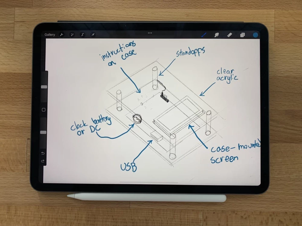
To start with, I chose to draw a sketch of my final project using Procreate on the iPad Pro. Procreate is a raster program, which means that you using pixels instead of vectors. This means that the end result is not freely scalable without the loss of quality.
Procreate is a fairly simple program, and I mostly use it for recreational drawing, although I prefer the feel of paper over the stickiness of glass.
When starting out with a new piece, I first choose the brush I want to use using the brush menu:
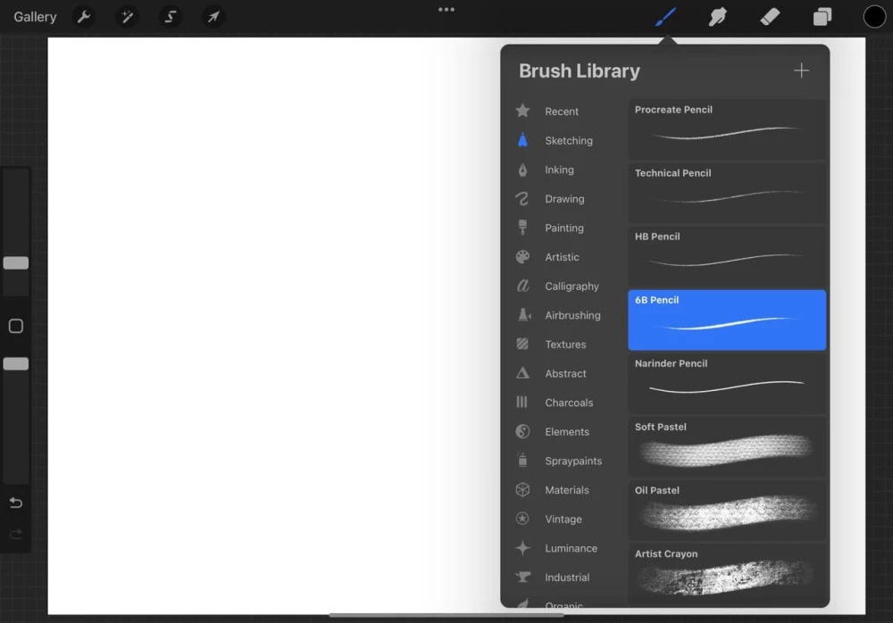
I really like Procreates pencil textures, and for this drawing I'll be using the "Technical Pencil" -brush. I usually don't bother messing around with the brush settings, which can be done by clicking on the brush name.
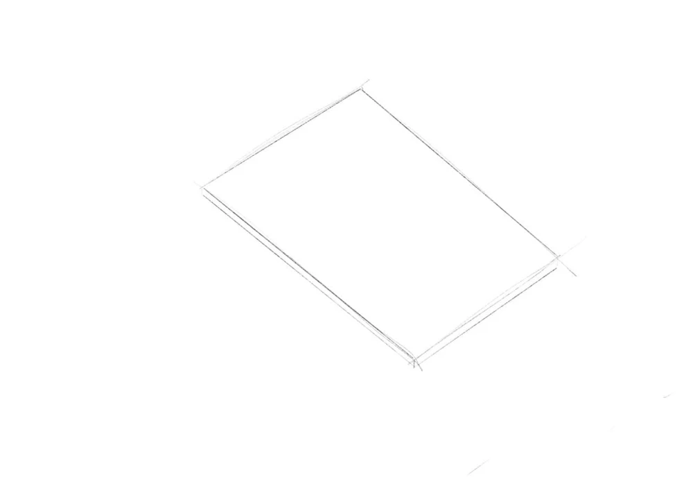
After this I start drawing. With Procreate, if you hold down after drawing a line, Procreate smooths it out for you, which is really nice for technical drawings.
For each part in the design (acrylic pieces, standoffs, pcb, screen etc.) I created a new layer. This makes it easier for erasing mistakes, as you don't screw up previous work. This can be done from the layers menu. Here you can also remove or duplicate layers, which I did for the acrylic layer to create two of them.
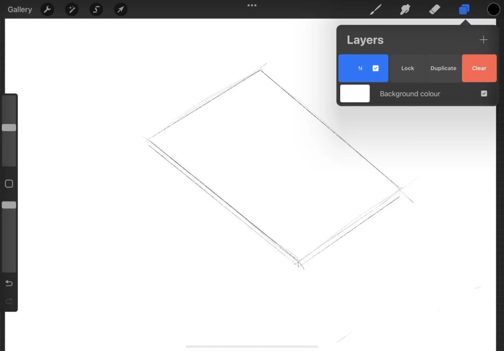
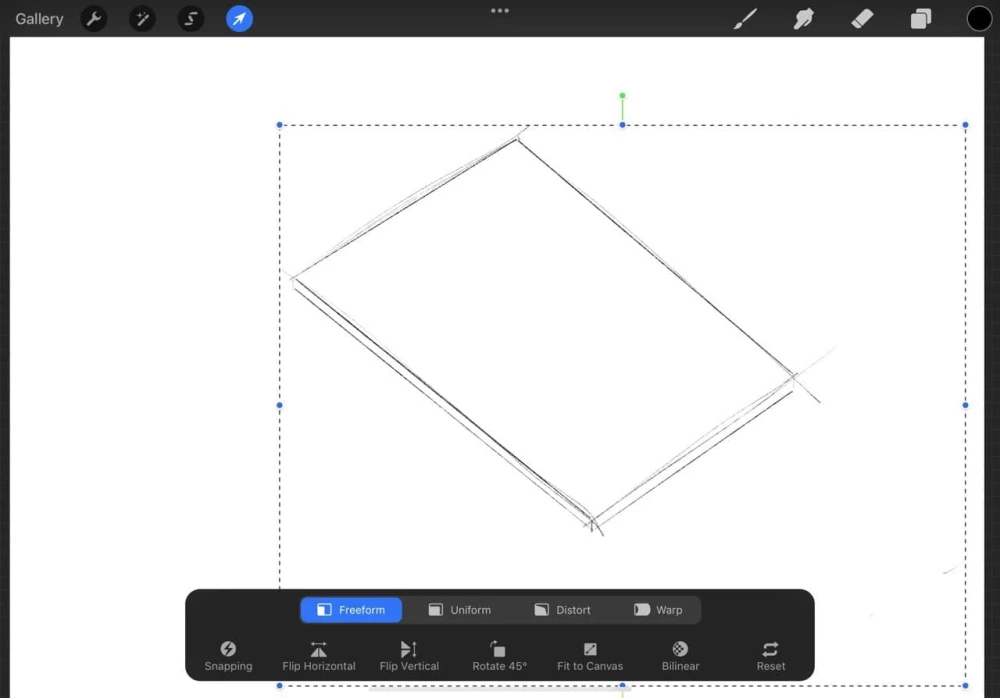
Moving layers happens with the Move tool, and you simply drag the layer around where you want it. Here you can also scale the layer, which happens accidentally more often than I want it to.
In my final design, I have a PCB sandwiched between two acrylic plates, with standoffs for spacing. The PCB is powered by either a clock battery or DC, DC is probably easier but less clean and portable. In addition to this there's the USB port for plugging in an USB stick with the broadcastable media, and a case-mounted/integrated antenna. Oh and a microcontroller for the actual processing of the files, which I forgot from the sketch :'D.
In the top acrylic there is a mounted screen, which is connected to the PCB. This is for displaying status for the user, and possible debugging. Above the screen, there are engraved instructions.
Vector graphics
As opposed to raster graphics, the base unit of vector graphics is a vector. This means that you draw using vectors, instead of pixels, resulting in work that is freely scalable without loss of quality. At least for me, vector graphics programs took longer to get used to when compared to raster graphics, but now I'm fairly comfortable with them. For this exercise I went with Adobe Illustrator, as that is what I've used the most.
In this part, I'll be doing the top acrylic plate template for laser cutting. This means the holes for screws and engraved instructions.
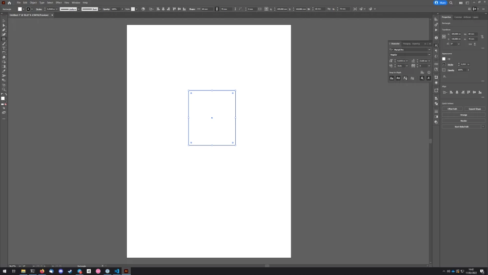
I started off with a rectangle:
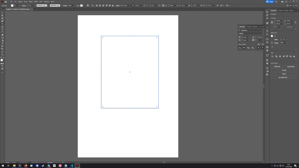
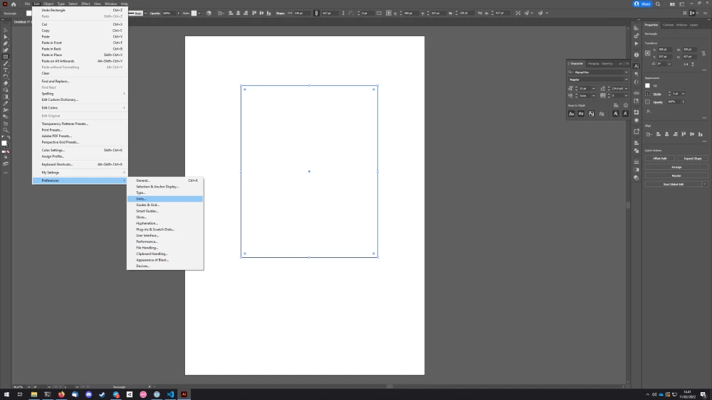
When I went to resize it, I noticed that my Illustrator units are set to points instead of millimeters, which is required for laser cutting. I changed this in the units menu:
After this I resized my rectangle to 70mm x 60mm, which is around what I think the final result will be:
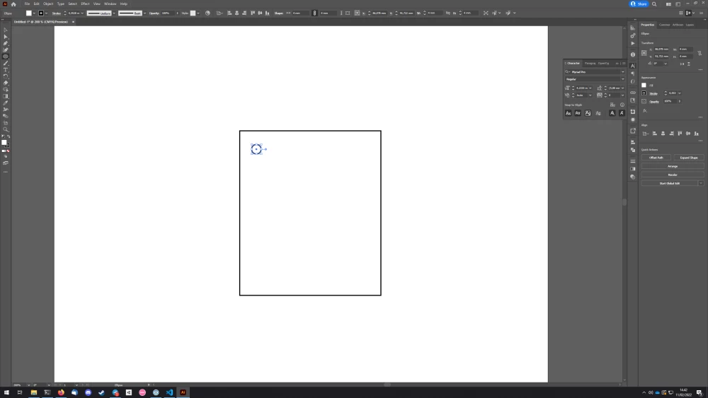
After this, I created a circle with a 4mm diameter. This means that an M4 bolt will fit through.
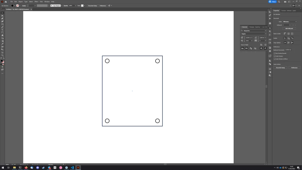
Next I duplicated it for all four corners, making sure to align them all the same way:
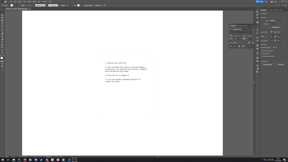
After this I moved on to placing and scaling the instructions on the top part of the acrylic:
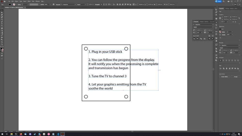
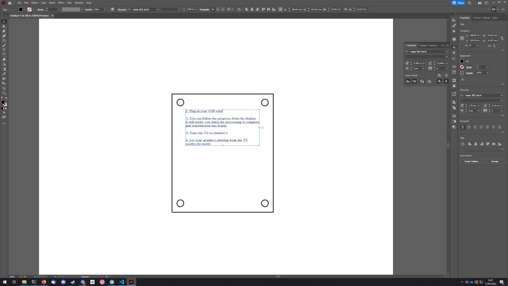
After this I changed the stroke size to 0,01mm, as is required for the laser cutter at the Fablab here. And here is my final result:
This also needs the screw mounts for the screen added, as well as a hole for the display cable. But I think I will do those in the next step with Fusion 360.
3D modelling
I wanted to do my modelling in Fusion 360, even though Autodesk is Bad. I would really like to learn FreeCAD, but at the moment I'm a bit more comfortable (not much) with Fusion, and it's the industry standard, so might as well.
I set of to design the enclosure for my PCB. My idea here was to create two acrylics blocks that the PCB gets sandwiched between. The acrylic pieces would then be spaced by standoffs and would be screwed together from the corners. I am still unsure if I'm going to do threads in the acrylic itself, or whether I'm going to just tighten it with a nut. The idea is to make the enclosure so that it can by used standing up or lying down flat, with all the ports accessible from either position. I'd also like to integrate the antenna into the case in some sleek fashion, but I've yet to think how.
As a placeholder for the complete steps, you can view 11 minutes of my glorious fumbling around in Fusion 360, trying to design an enclosure for my PCB. It took me longer than expected, but I'll probably do another run with photos instead of a video. And an actual finished end result.
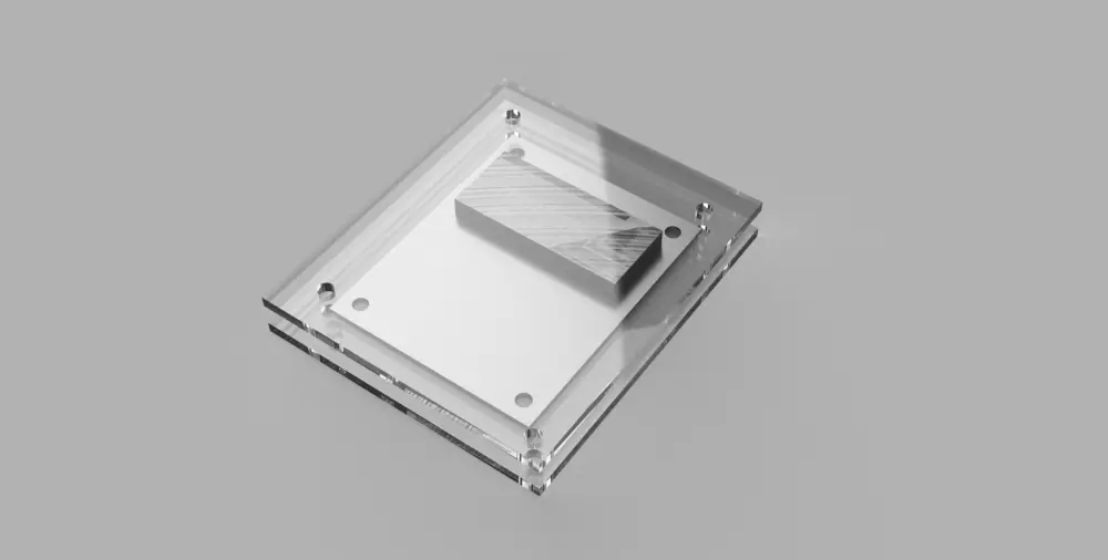
I also tried rendering in Fusion 360 for the first time. Below is what the end result looks like. I will add steps on how to actually do this once I do another run of the enclosure design.