Week 05: Computer-Controlled Cutting
This week, our assignment was to
- Characterize your lasercutter's focus, power, speed, rate and kerf.
- Cut something on the vinyl cutter.
- Design, lasercut a parametric press-fit kit that takes into account the kerf and can be assembled in multiple ways.
- Document all of the points above in a new page on your documentation website.
- Submit a link to the assignment page.
Vinyl cutting
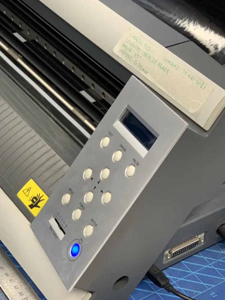
To start using the vinyl cutter, turn it on using the power button, if it's not turned on already. The power button is in the lower right corner of the control panel
For material, you can find some in the box with leftover pieces. Zero waste baby!!!
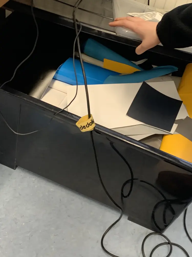
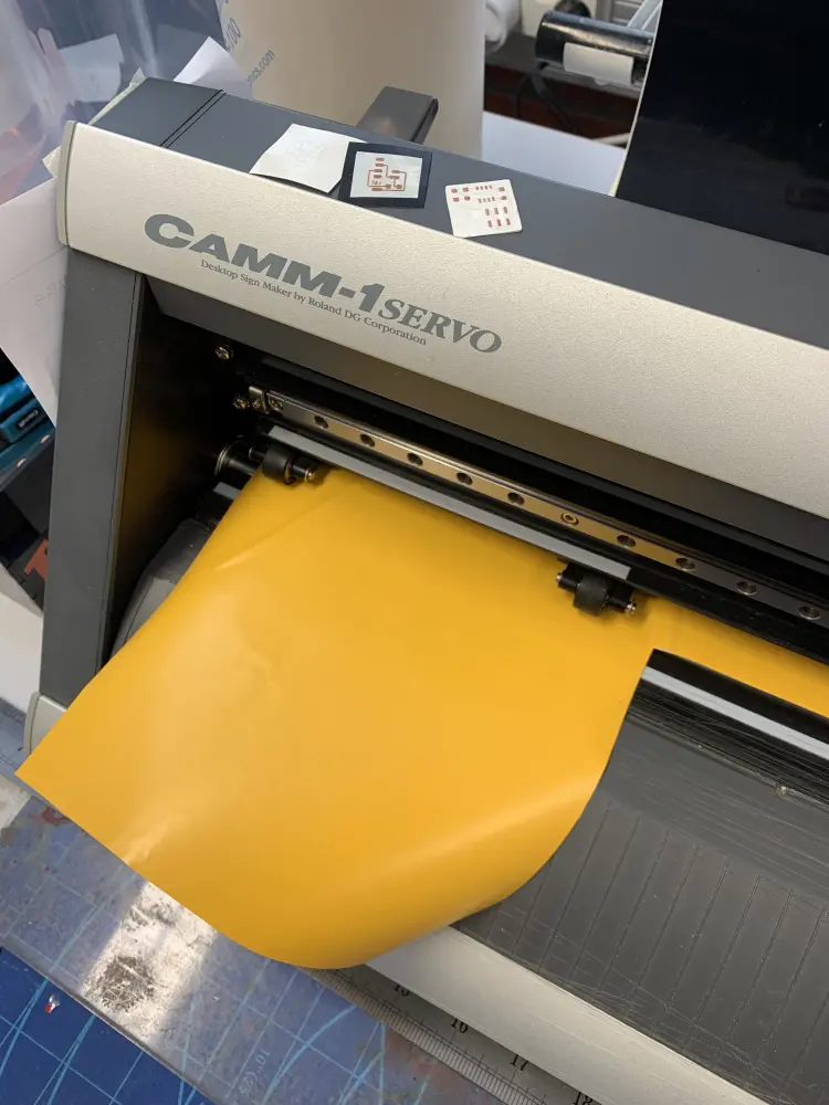
First place material in the cutter. Use the rolls to calibrate the width. Make sure to cover the sensor in the machine. Use the lever in the back to clamp it the material down.
Make sure the rolls are within the white areas marked on the cutter! The leftmost roll must be in the leftmost white area, but the rightmost roll can be in any of the areas.
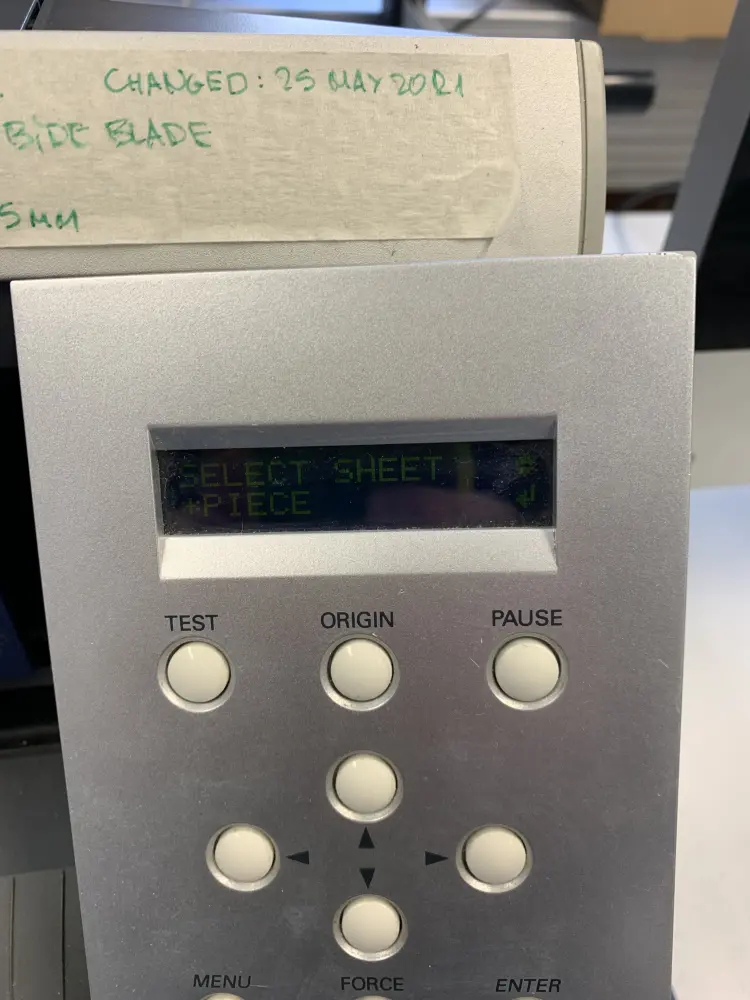
After this, select the sheet mode using the arrows. Possible modes are 'Roll' for cutting from the roll, 'Piece' from cutting from a piece of material, or 'Edge', which is the same as 'Piece', but ignores the height of the piece. I went with 'Piece', as I'm cutting from a piece of material.
Make a test cut by pressing "Test". Check if the knife penetrated the material fully. If everything seems to be alright, nothing more needs to be done. If the blade did not cut through, press "Menu" then go to "Condition" and change the Force. 80g of force should be enough for all the vinyls in the Fablab.
There is also a setting for blade speed. 1cm/s is good for precision, but takes longer to cut. Increasing speed lowers the precision.
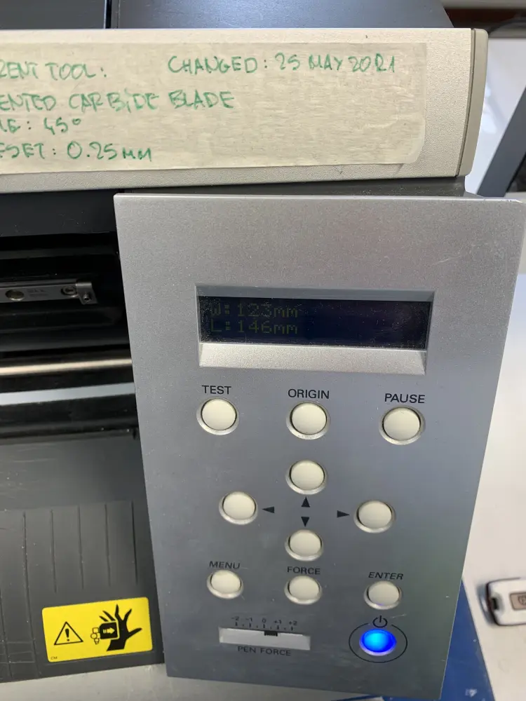
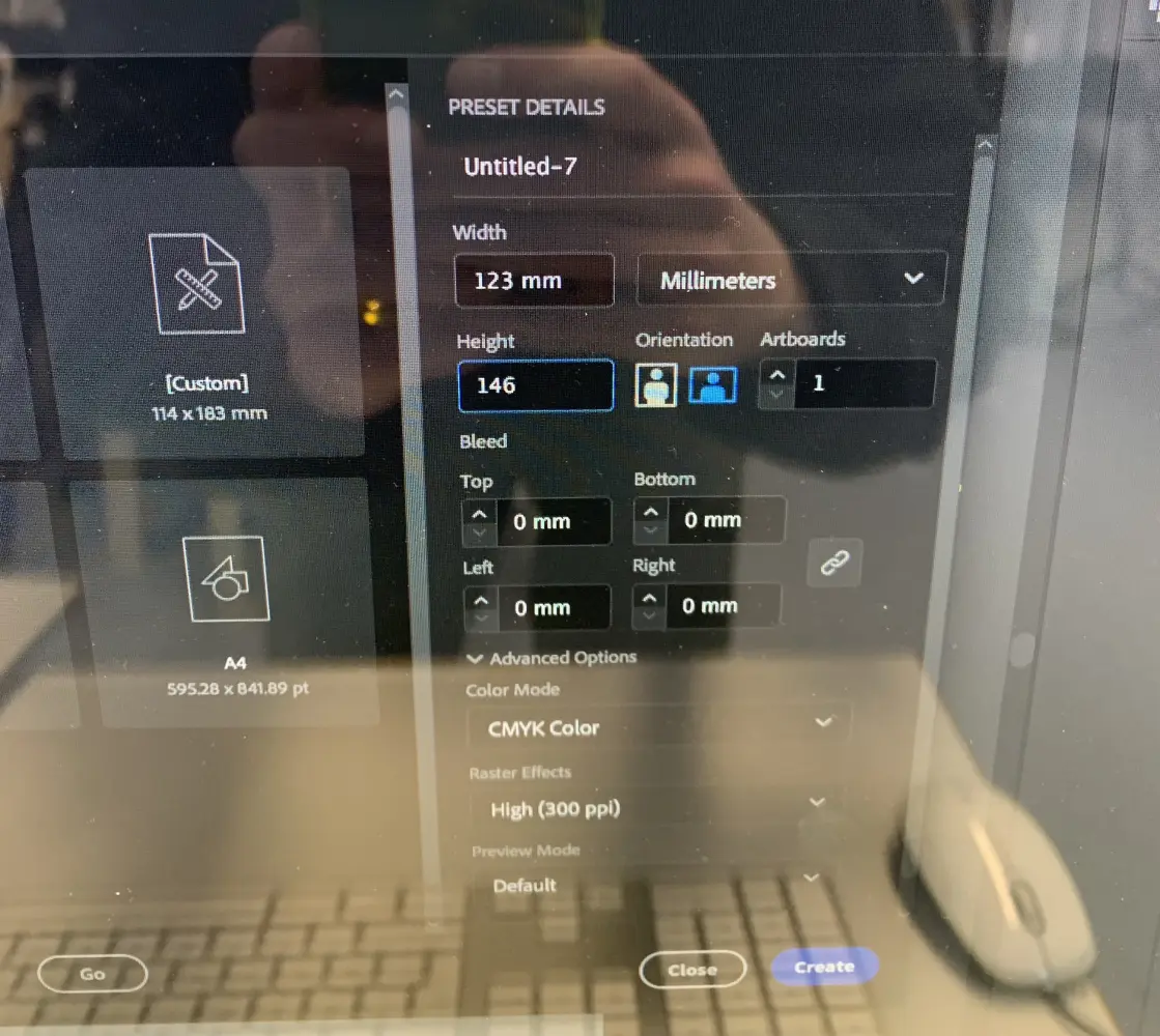
After this, you can open Illustrator and create a new artboard with the same width and height as shown on the vinyl cutter.
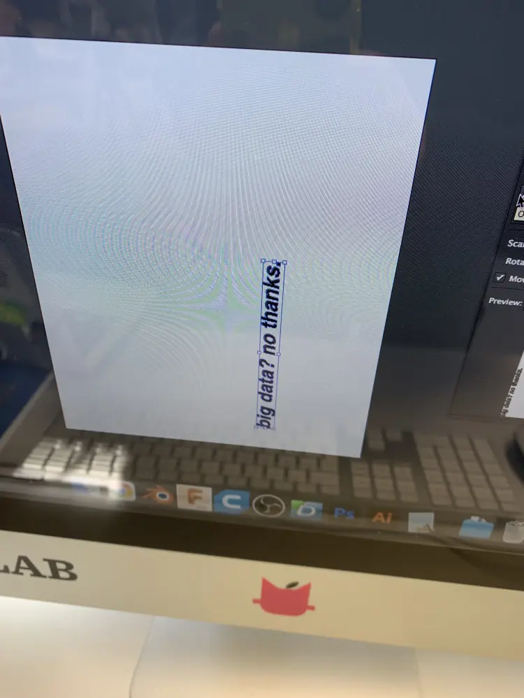
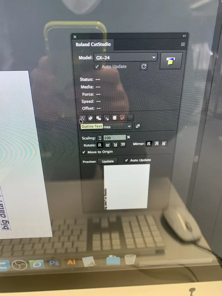
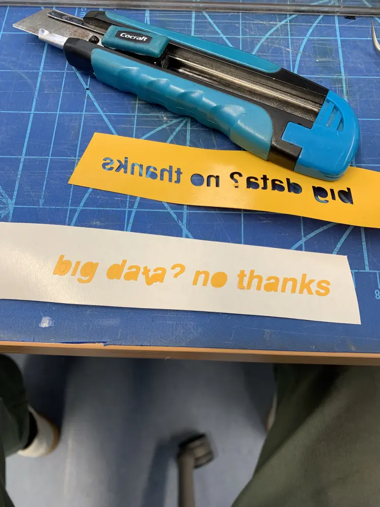
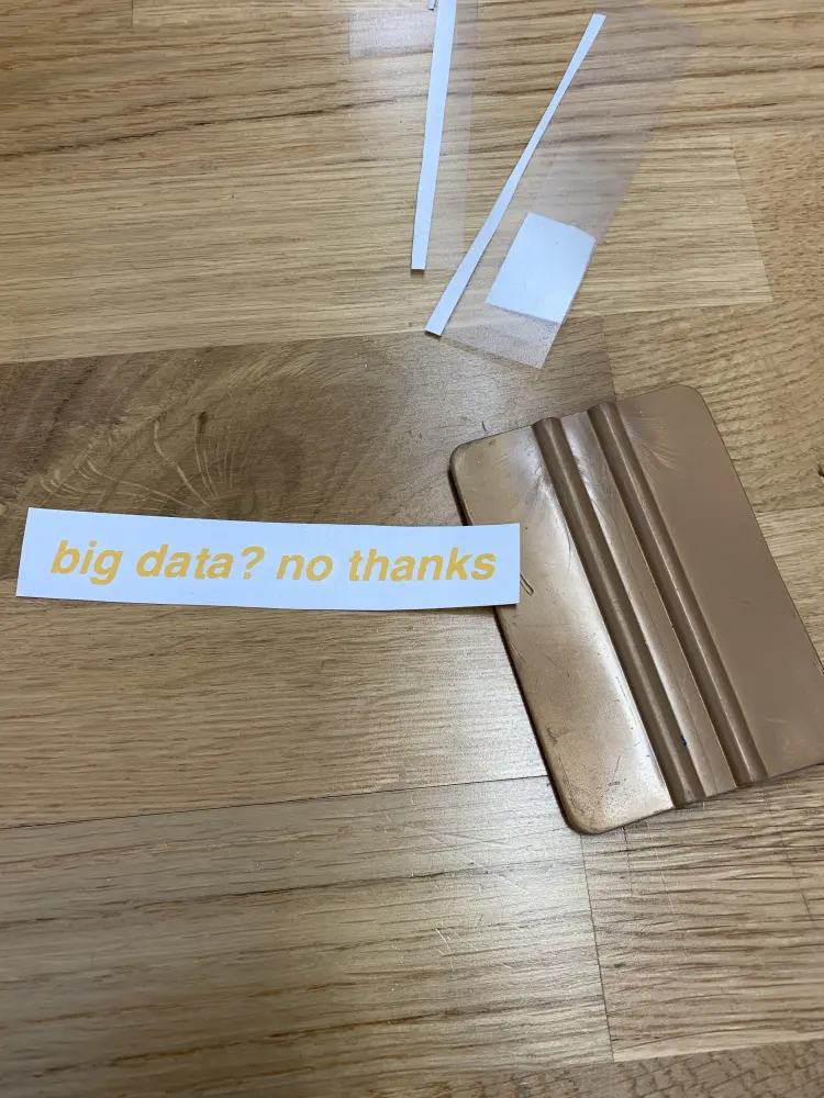
Insert the stuff in the artboard you want to cut. In my case I typed the text "big data? no thanks."
Select "Outline Text" from the Roland CutStudio. Make sure Move To Origin is checked. Press "Output the Paths" Once everything is ready. Press "Cut" to cut.

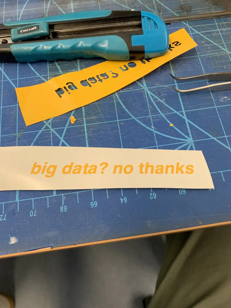
After cutting make sure the cut is through the material with tweezers
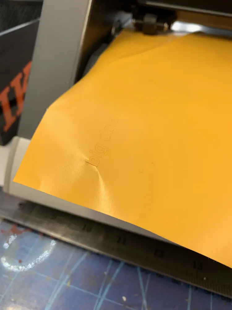
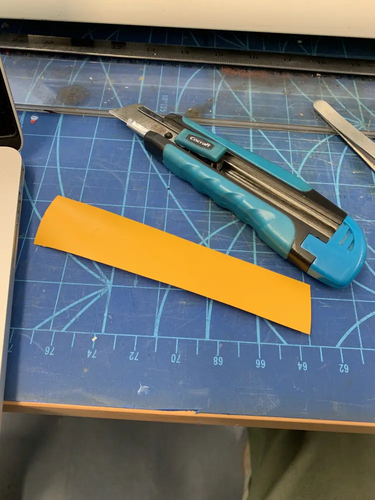
If it's cut through, Press "Menu" and select "Unsetup" to pull back the blade. Lift the lever and pull out your material. Trim material to wanted size with a box cutter.
After this, pull the excess material out with tweezers. This tedious, and as you can see from the pictures, it can go easily wrong. Mistakes can be somewhat fixed though.
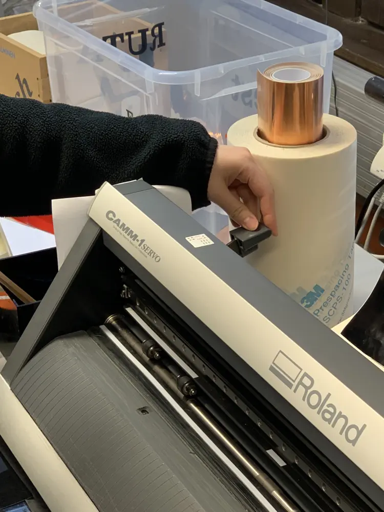
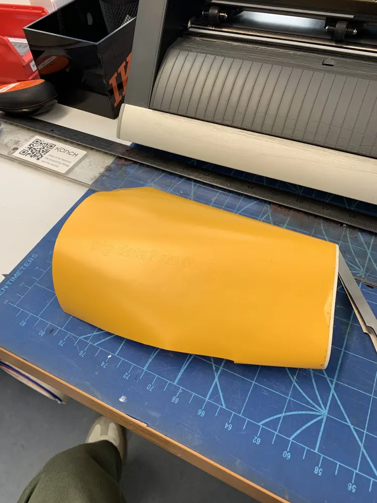
After removing excess material, throw it into the trash and apply the transfer tape on top the vinyl. using the spatula. The trash box is on the left side of the vinyl cutter.
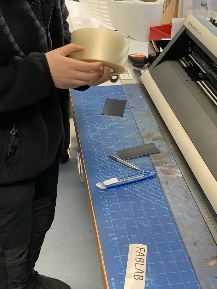
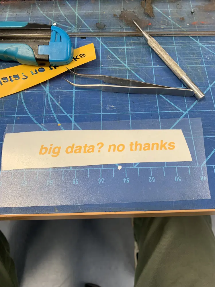
At this point I trimmed the edges of the stickers, and used spatula again to apply the transfer tape. It would've probably made more sense to trim it before even applying force with the spatula, because the transfer tape sticks to the desk also.
After this, you can peel the tape backing and apply your decal to the object of your choice. Be careful, as you can pull the decals out of the transfer tape if you move too quick.
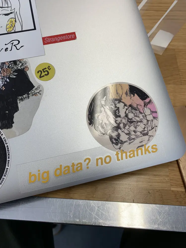
Add some pressure again with the spatula to fix the sticker to your object. Pull back the transfer tape slowly, and tada! Your sticker is now fixed.

Heat-transfer vinyl
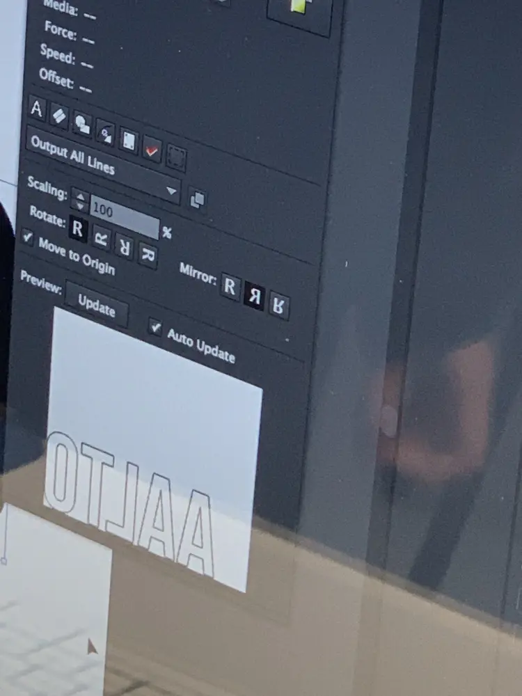
For heat-transfer vinyl, you need to insert the vinyl the less glossy side up, i.e. the glue side up. Thus you also need to mirror your design in Roland CutStudio.
KUVA
For heat-transfer vinyl you don't need to use the transfer tape, you just trim the material and remove the excess vinyl. Then you need to move over to the heat press to apply it.
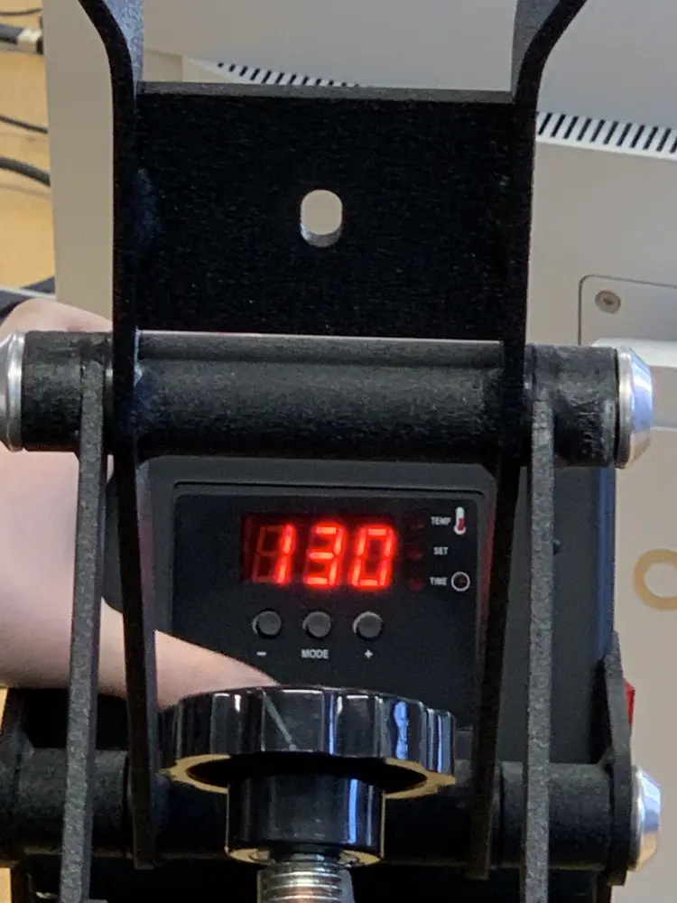
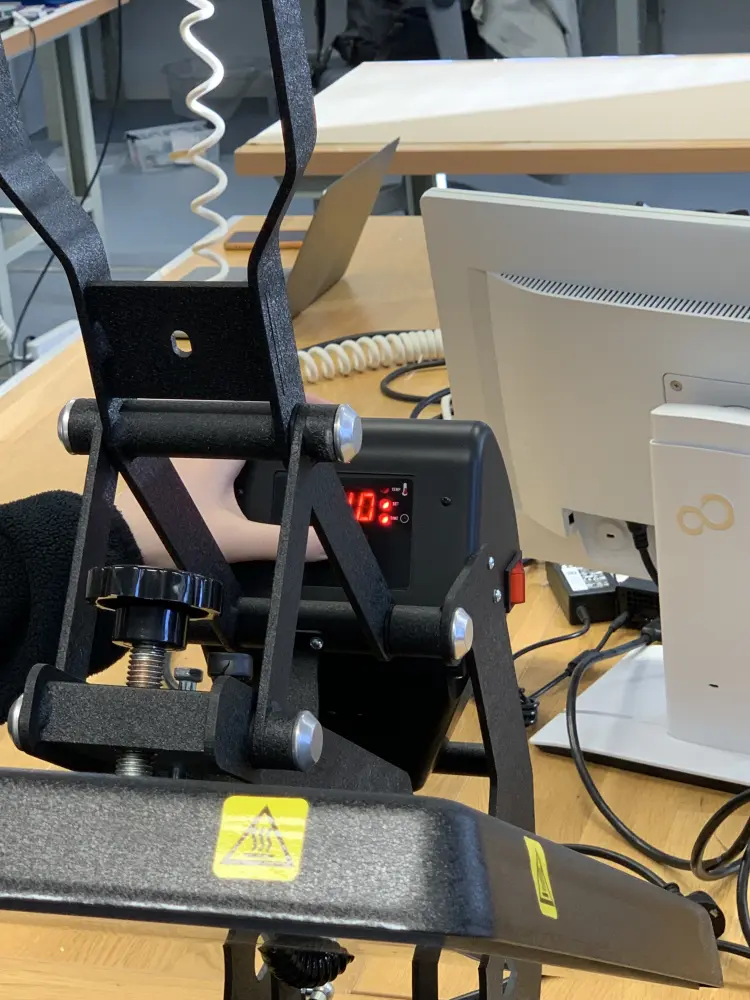
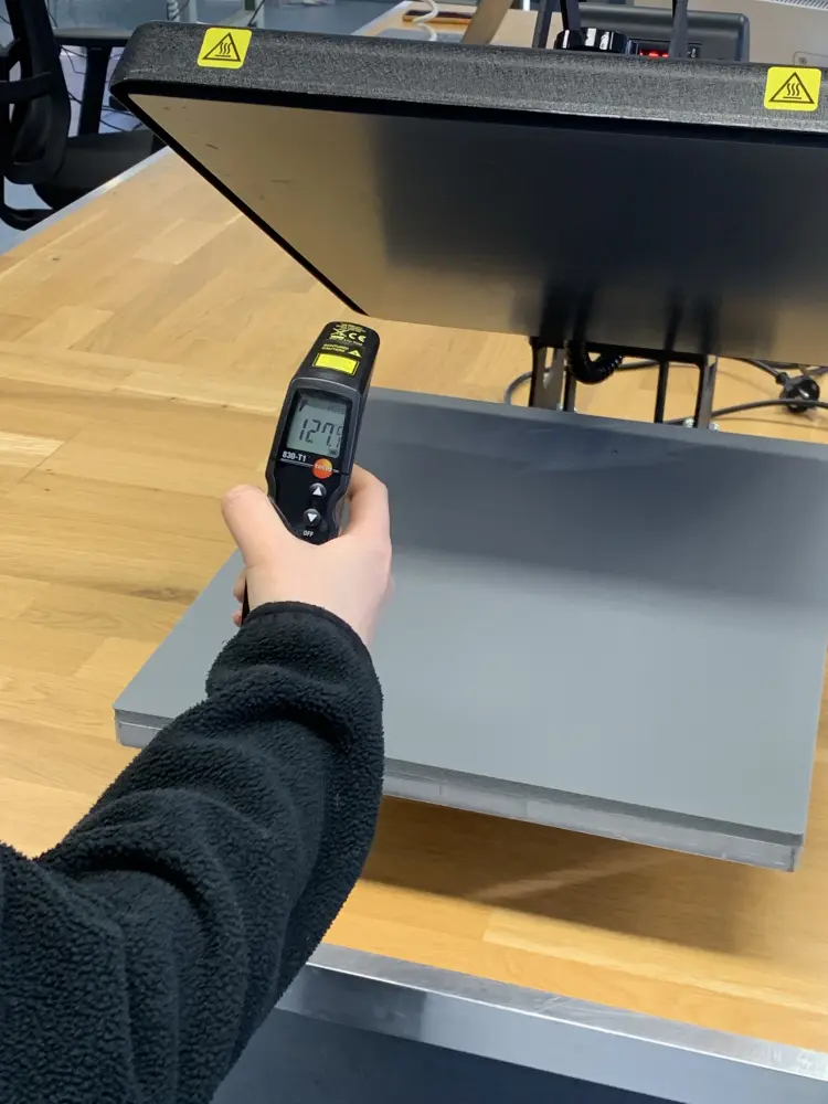
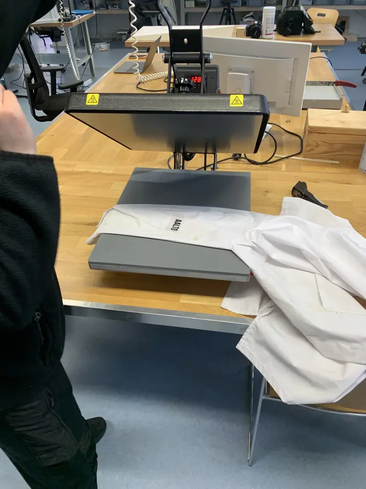
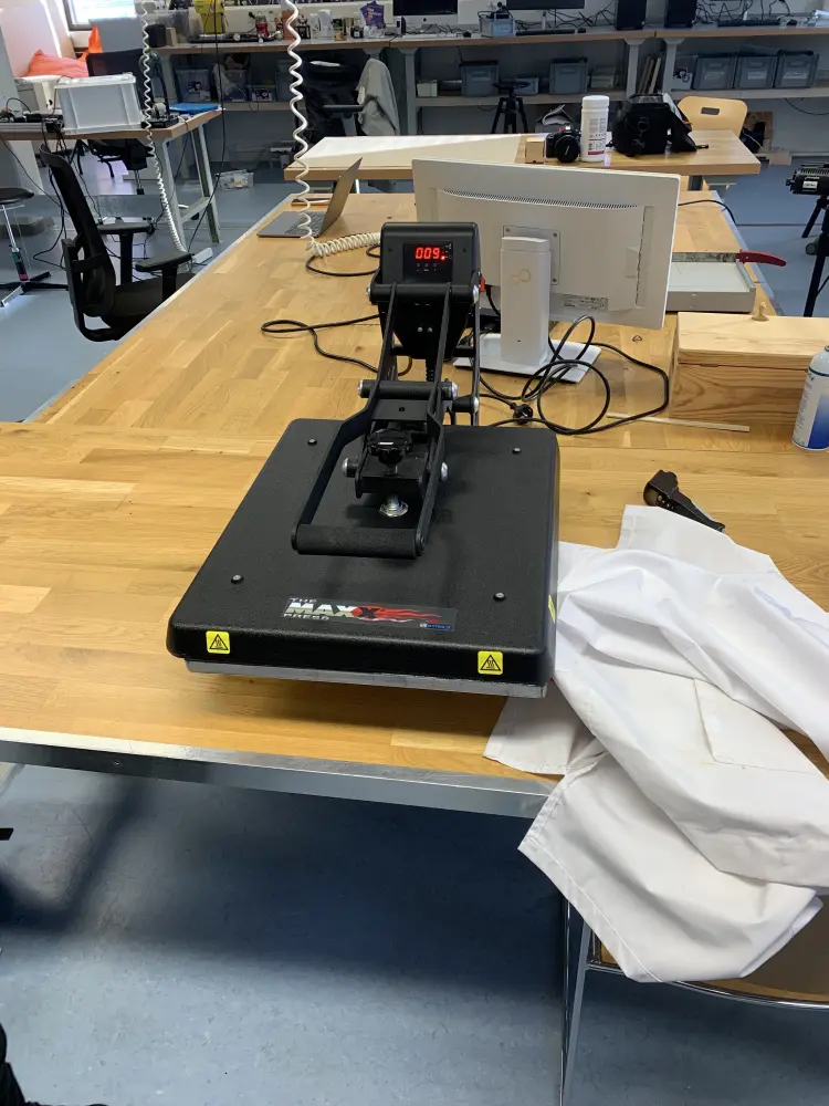
First, turn on the heat press using the power switch. The press takes about 10 minutes to heat up. You can see the temperature on the screen, although minimum it can show is 90 degrees. To confirm where it's going, use the thermal gun to check.
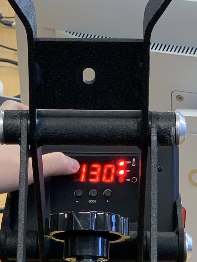
For heat-transfer vinyl, 130 degrees Celcius is the temperature we need to use. Use the mode button at the top to cycle to the temperature set mode (the "Temperature" and "Set" lights will light up) to change the temperature.
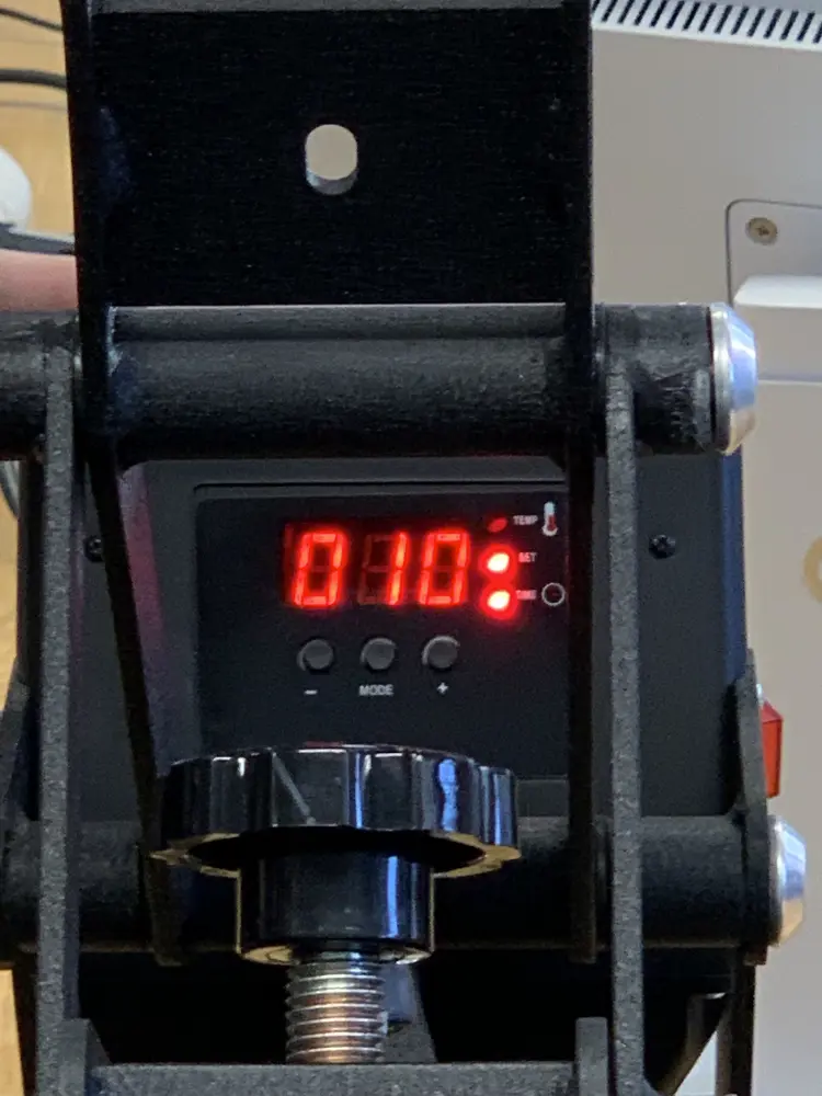
After setting the temperature, set the time. This can be also done by using the mode button (the "Set" and "Time" lights will light up). Units here are in seconds. For heat-transfer vinyl you need to use 10 seconds of time.
Now you're good to go! First place your fabric in the press and pull down the press. Hold for 3 seconds to preheat the fabric, and then lift the press and pull your fabric out. Be careful, it's hot!
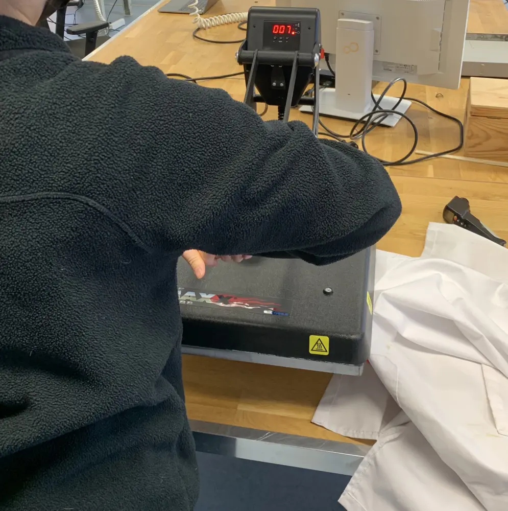
Put your heat-transfer vinyl on the fabric where you want it to and move the fabric under the press.
Clamp down for 10 seconds, the machine beeps when the time has passed. Lift the press and remove the fabric. Be careful again, it's even hotter!

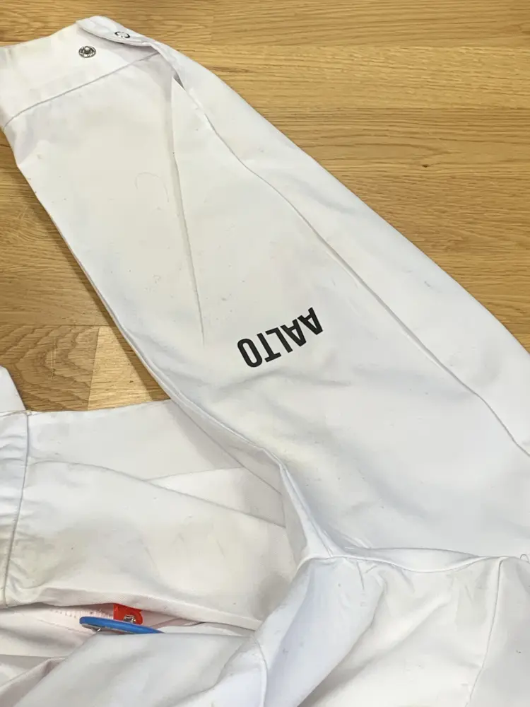
Give the fabric some time to cool down before removing the film on top. After your film has been removed your piece is now done! Congratz!
Copper sheets
For copper sheets, you cut your pads and traces, then you cut an epoxy mask, that protects the traces but shows the pads for soldering. We didn't go too in depth with this, but I'm really interested in learning more about this.
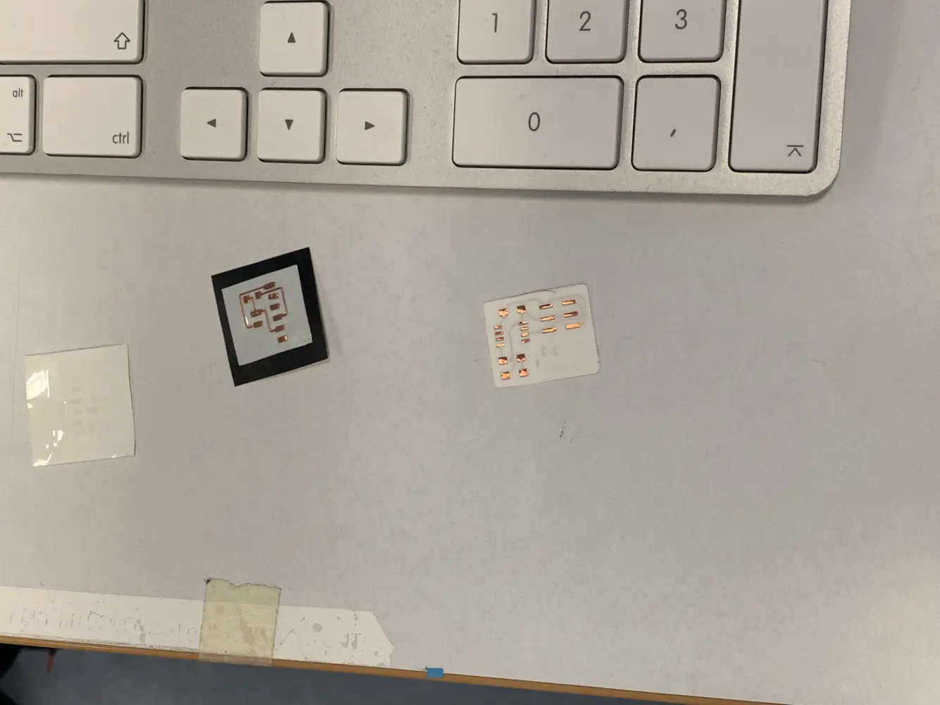 From left to right: Epoxy mask, traces and pads cut from copper sheet, epoxy mask applied to copper sheet.
Laser cutting
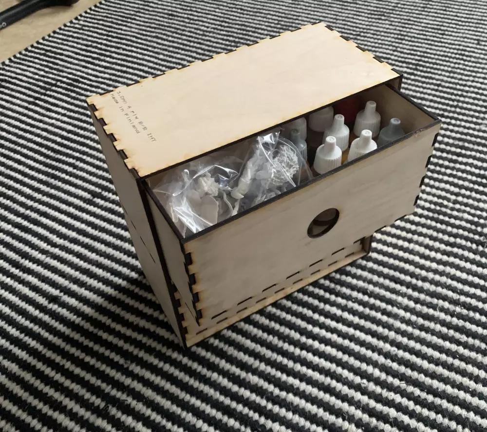
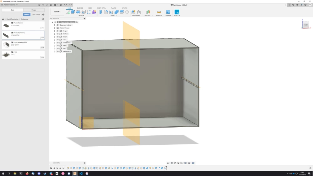
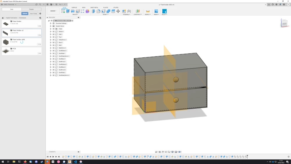
For my press-fit kit exercise, I decided to do a small drawer for my miniature paints. I designed it in Fusion360. It's mainly just a box with fingerjoints, but it has 5mm rails down the middle, which allows two drawers to be placed on top of each other without interference. The drawers themselves are fingerjoint boxes as well.
I wanted to make everything parametric, as was instructed, and in hindsight I succeeded quite well. There were only a few features that would break when I would change the parameters, but more on that later.
Design
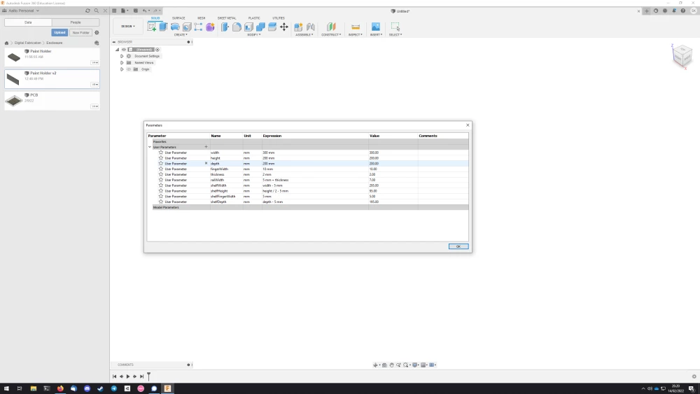
I started by inputting all the parameters I thought I would need. Well planned is half done after all.
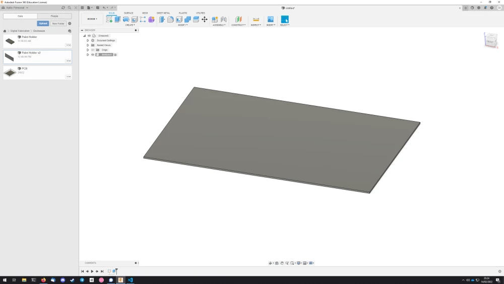
Then I moved on to creating the bottom, using the parameters width and depth as it's dimensions and extruding it by 2mm using the thickness parameter.
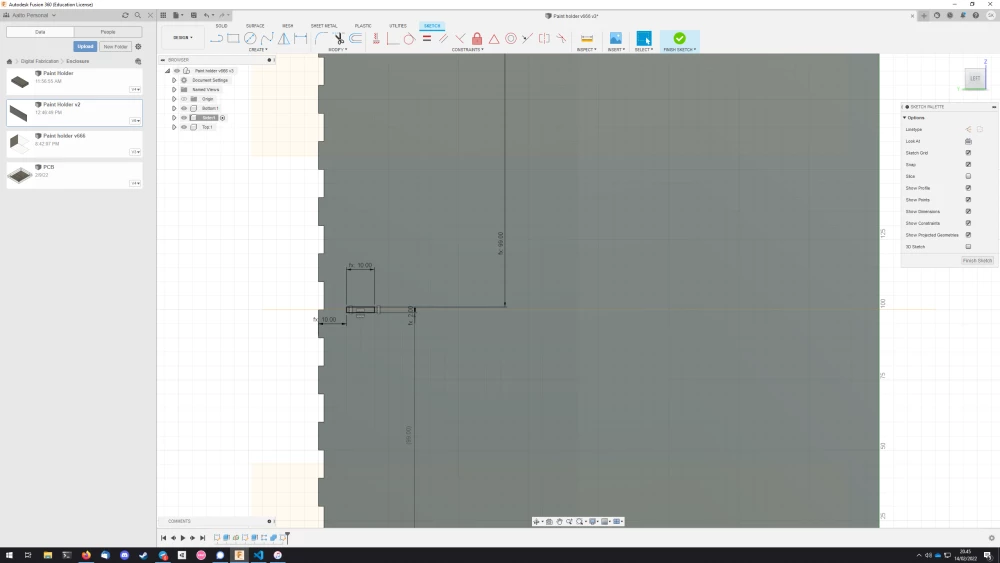
Then I moved on to creating the fingerjoints. I started by creating a sketch along the edge of the bottom plane, and adding a new rectangle with the dimensions thickness x fingerWidth. Then I snapped the rectangle into the edge of the bottom, and used the Dimension -tool to ensure that it was fingerWidth away from the shorter edge of the side.
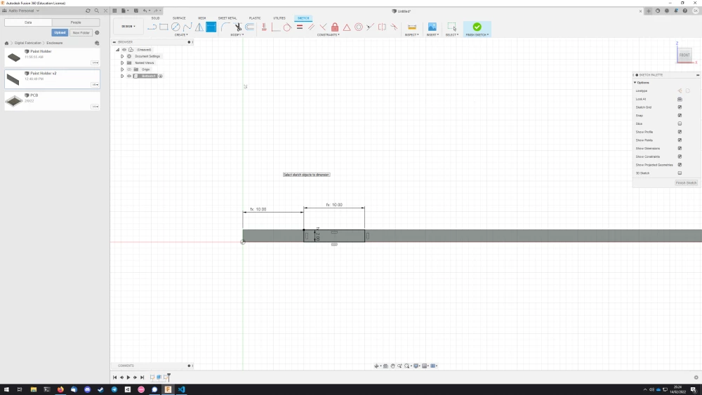
After this I selected the rectangle I just created, and extruded it inwards by thickness.
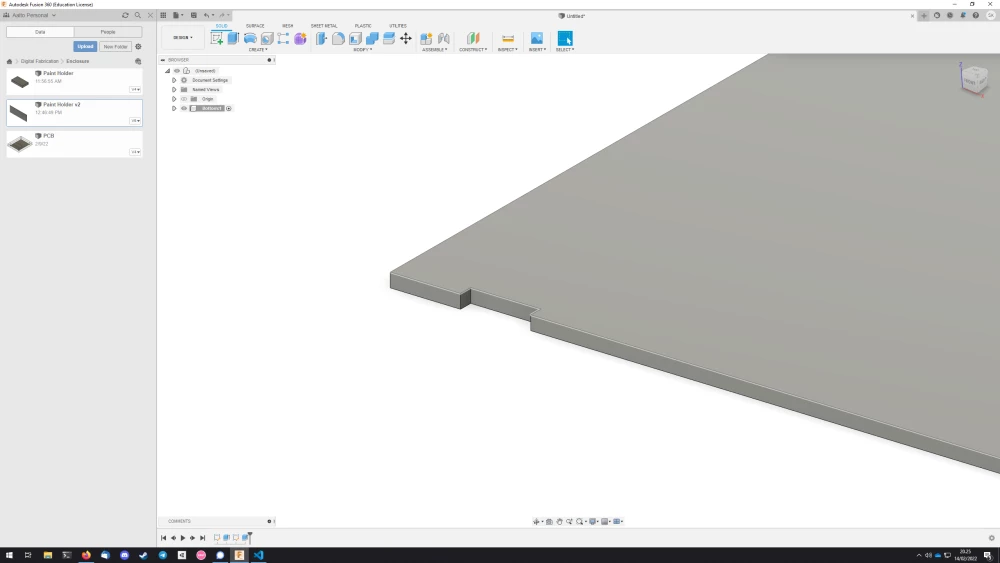
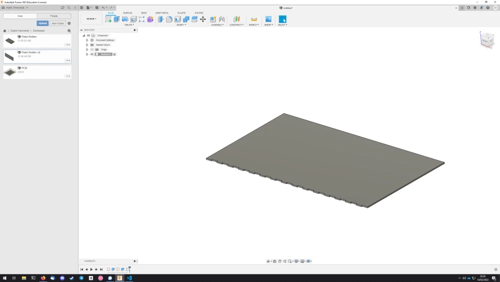
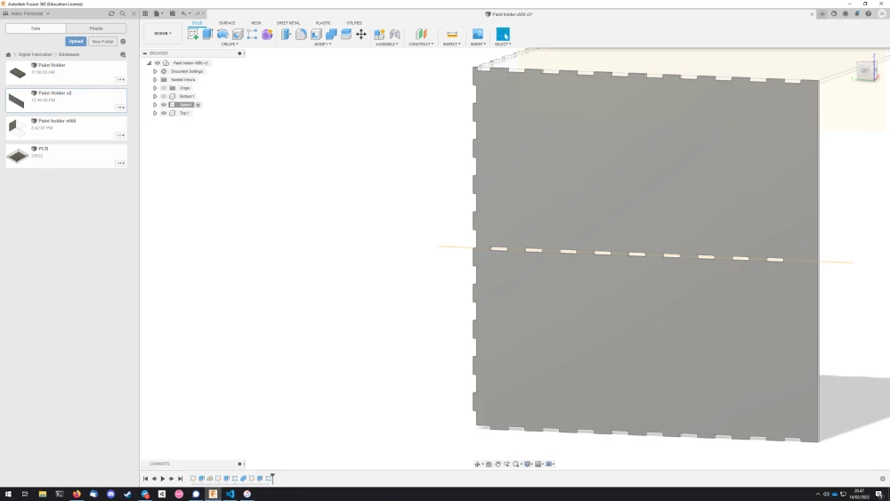
Then I would repeat this feature I just created by creating a Rectangular pattern along the side in Fusion 360.
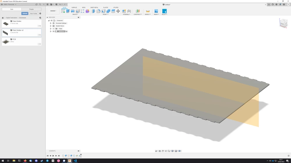
After this, if I would need the joints to be on the other side, I would create a midplane for the component I'd be working on, and mirror the joints to the other side using the midplane as the mirror plane.
This process would get incrementally easier, as once you have more and more of the faces of your box, you can use the Combine tool to carve out the finger joints for your pieces using the already existing pieces.
As for the rails, I first created the holes.
I started by creating a sketch for the side of the box, adding a rectangle that was essentially the same one as used for the finger joints. Then I ensured that it would be in the middle of the box using the Dimension tool and constraining it to height/2 - thickness/2.
After this I followed the same procedure as for the finger joints: extrude inward to create a hole, then use the Rectangular pattern to copy it. However, here I did not extend the Rectangular pattern all the way to the front of the box, as I thought it would be cleaner that way.
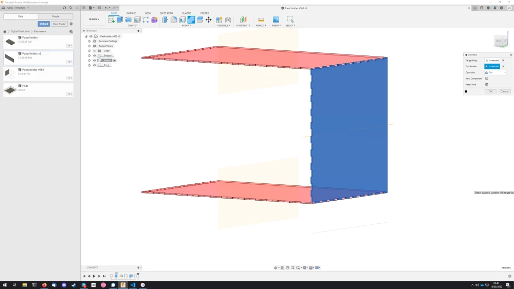
As for the rail itself, I would create a sketch in the same place as the holes, but with a width of shelfDepth, making sure to constrain it to the center as well. Then I extruded a new body with a thickness of thickness + railWidth. Then I used the Combine tool to carve out the part of the rail that was overlapping with the side, leaving only the fingers.
The rail is actually one of the parts that ended up breaking when changing the parameters, particularly the thickness. As I had not been careful enough to constrain the sketch for the rail on the outer edge of the side piece, it ended up not moving with it as I grew the thickness, and as a result the fingers of the rail would not be long enough.
In addition to this, I found the Rectangular pattern and the Mirror operations to break whenever I would change the dimensions. Also some bodies would move around whenever I would change the dimensions, which was super weird. It was also pretty frustrating when I would adjust the dimensions at the laser cutter to make the box smaller, as this would mean that I'd pretty much have to do the design from the start. Goes to show that there is a lot to learn.
Cutting
The laser cutter is a lot more prone to accidents compared to the vinyl cutter, and thus shouldn't be left unattended due to the risk of fire.
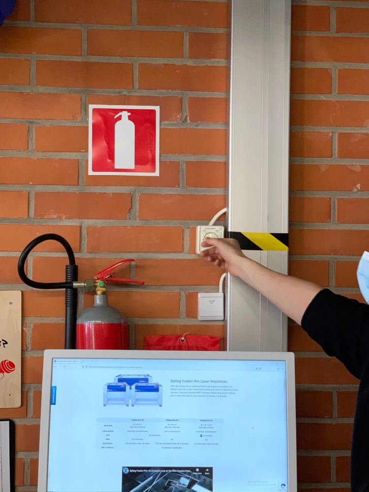
First you need to turn on the ventilation using the knob placed on the wall behind the computer. The digit tells you how many hours it's going to be on, so crank that sucker to 11 because you don't want to breathe the fumes that result from cutting.
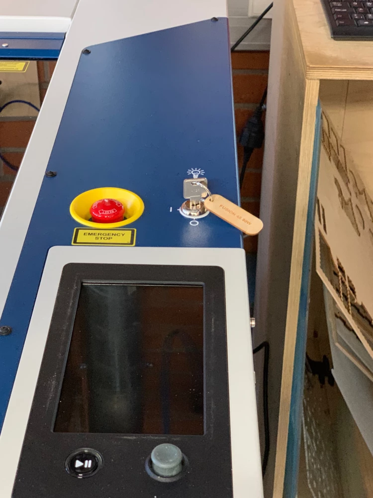
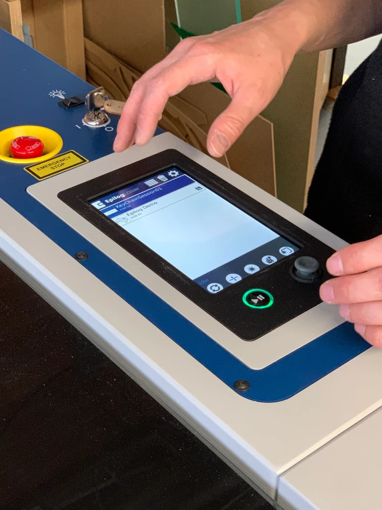
Then, to turn on the laser cutter at Fablab, first turn the key to the "I"-position on the laser cutter, then show the white key card to the red box next to the computer.
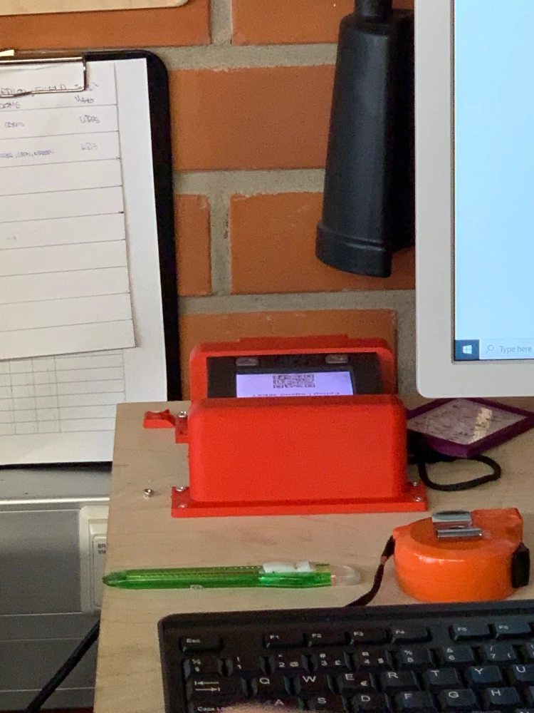
The red box is will flash and beep after ten minutes. When this happens, press the button with the checkmark on it, otherwise the laser cutter will turn off. This system is in place to make sure that the laser cutter is not left unattended.
After this, you can prepare your files in Illustrator. Set the stroke to 0,01mm and ensure that the color of the stroke is #000. It's also a good idea to simplify the paths using Object > Paths > Simplify. It's also at this point where you would do the kerf adjustment by using Object > Paths > Offset paths.
Incidentally, the kerf adjustment is where I struggled the most. I heard a value of 0,1mm being thrown around the lab, and decided to use it. I ran a test with my side piece and the rail. This resulted in a pretty tight fit, so I thought that I could just go ahead with the design. What I failed to realize was that fitting the rail with 0,1mm kerf adjustment into its hole in the side with -0,1mm kerf adjustment is different from fitting two finger joint pieces with 0,1mm kerf adjustment together. So, for my initial run, the kerf for the finger joints was too loose and the shelf wouldn't stay together.
This kind of broke my spirit for a bit, as I had just wasted huge amounts of material on what was essentially now scrapwood. I took a small breather and decided to cut my shelf size from 30cm x 20cm x 20cm to 20cm x 10cm x 10cm to reduce further material usage. I also made a small test piece in Fusion 360 that I then laser cut with different kerf compensations. It's a good idea to engrave these with the kerf adjustment you are using to not mix them up.
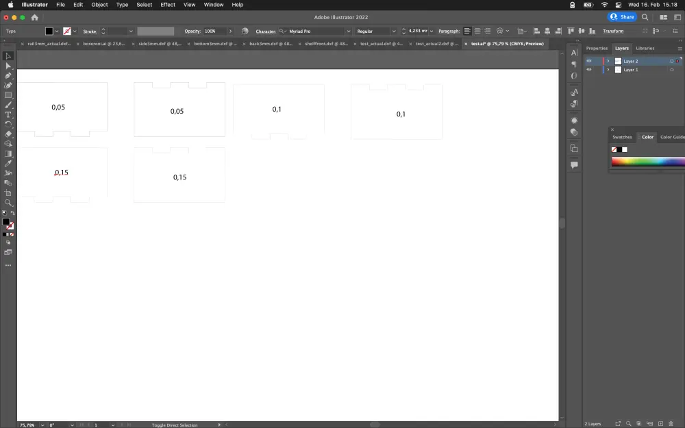
With these test pieces I was able to figure out that on the FabLab machine, 0,15mm of adjustment is still a bit too loose for finger joints, at least in my experience with 3mm plywood. 0,17mm is tight enough that you have to hammer the joints into place, but you don't really have to fear that it's going to fall apart. In hindsight, 0,16mm would've probably been perfect.
After getting the kerf figured out, we come to the actual laser cutting. The way it works is that you send the file from Illustrator to the Epilog software using File > Print. Make sure to set the Media Size to "Custom", but other than that you should be good to go.
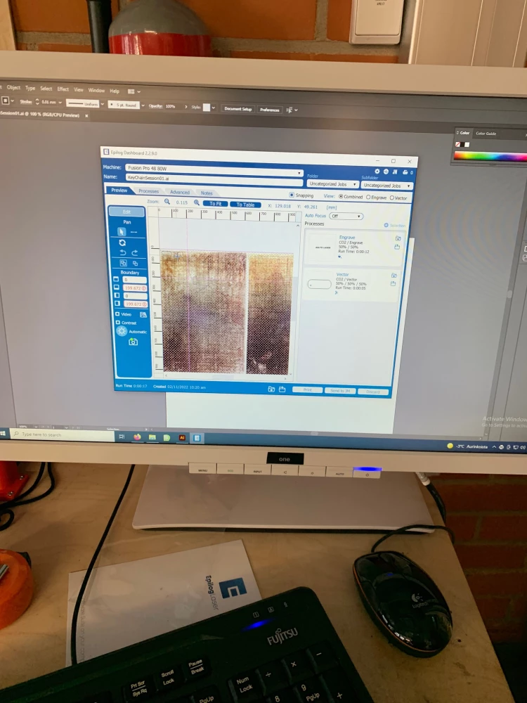
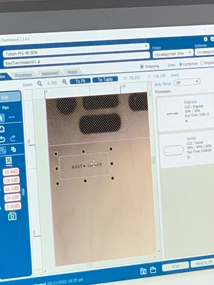
The Epilog software (that I can't remember the name of for the life of me) is where you adjust the cutting job before sending it to the printer. Here you can place your design on your material using the fancy schmancy drag an drop interface, since you can see material on screen from two cameras which are located in the laser cutter lid.
This sounds really cool, but in my experience the cameras wouldn't show anything 30% of the time, which would be really frustrating. Sometimes they would turn on randomly, sometimes they wouldn't. Usually a reboot of the machine would help, but it's still tedious. It would be good to learn how to manually place the cutting head on the material, if that's even possible.
Other than the placement, the Epilog software is fairly straightforward. On the right-hand side you can import material settings for the different phases of your design by clicking the folder with the downward arrow.
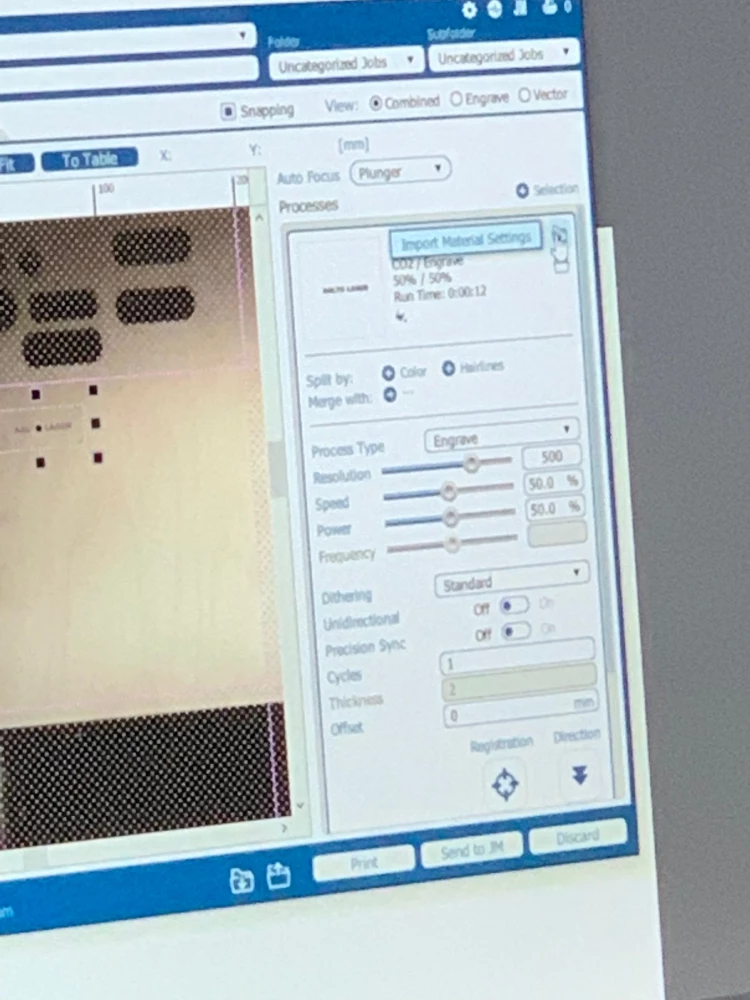
The default presets seemed to work fairly well. I had a few cuts where the laser wouldn't penetrate, but I think this is due to me forgetting to set the autofocus to plunger, which you set using a drop down above the material setup. It's very small, out of the way and thus easy to forget.
One feature I also used a lot was splitting the sections using color. I wanted to cut my holes first in the side pieces, so I would color them in pure red in Illustrator, and then split it in the Epilog software. This feature was nice and easy, 5/5!
After this you can send the file to the Job Manager using the button "Send to JM". If you run into connectivity issues here, first check that you've simplified your paths in Illustrator. If that doesn't work, try turning it on and off again™.
In the Job Manager, you can double check your settings, and hit "Quick Print" to send it to the machine.
Once you get your design to the machine, you basically just press play. But remember, stay vigilant. The risk of a fire is very real.
A list of learnings for future use:
- Before deciding on kerf, print small, labeled test pieces for both holes and finger joints with multiple values of kerf compensation.
- Remember to set the auto-focus to "Plunger" when working with the FabLab machine
- Figure out if you can manually set the starting point for the laser instead of relying on the camera.
- Remember to simplify shapes you get from Fusion360 to prevent buffer overload in the cutter.