Week 09: Computer-Controlled Machining
Our assignment this week was to:
- Participate one of the introduction sessions or watch instruction videos.
- Pay attention to what runout, alignment, feedrate and tool paths are.
- Design, CNC mill and assemble something big (meter scale). You will get a 1200x1200x18 mm sheet of plywood for your assignment. Make use of it.
- Document your process in a new page on your website.
- Add downloadable design files to your documentation page.
- Submit a link to the page on your documentation website.
Design
From the start I knew that I wanted to make a shelf of some kind. I thought of a few different designs, mainly with a slotted one, but ended up with a simple finger joint box, partly inspired by this Book/Shop -shelf I saw:
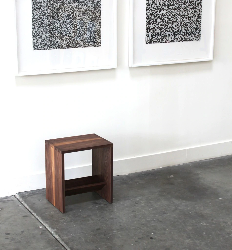
The initial idea was that this could also function as a bench, but the material and my final construction is definitely not strong enough for that. Maybe if I'd make it less wide it could work as a stool, but even then you'd probably end up with splinters in your backside.
For the actual design, I used Fusion 360. I probably could've done this in FreeCAD given that it's a pretty simple design, but currently I'm not really in the mood for struggling with a new CAD program. The final design itself was parametric, which made it really easy to adjust the finger joint sizes after I measured the actual thickness of the material. I also designed a small test piece to see if I needed to do some other adjustments for the finger joints to work. The designs for it have unfortunately seemed to have vanished off the face of the earth.
Finally, I exported the vectors for both projects as a .dxf file. One could've generated tool paths from Fusion 360, but I was really not in the mood for it, since I don't plan on using the CNC much if at all. Also given how energy intensive CNC machining is, I'm not sure how much I want to invest in the technology to begin with. Wood is also fairly easy to work with using hand tools, even if it's not as precise or as fast. But I have time and I'm really a precise person to begin with, so planet takes the win here for me.
Machining
For CNC machining, there is a Recontec 1312 at the Aalto Fablab. Due to the way the chip extraction is set up, only wood can be currently machined. This was a bit of a bummer personally, as I was looking forward to machining aluminium.
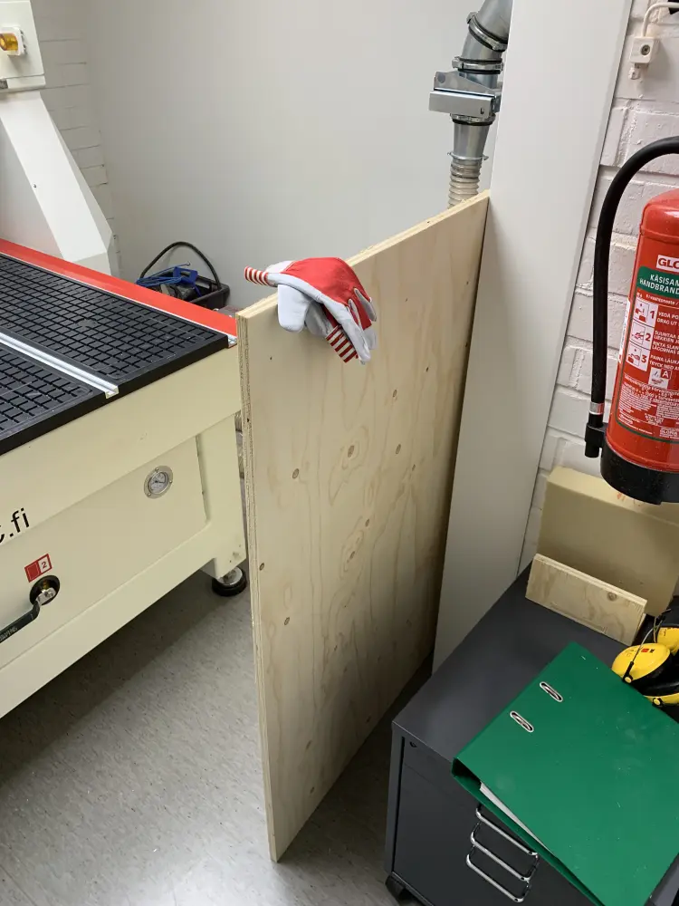
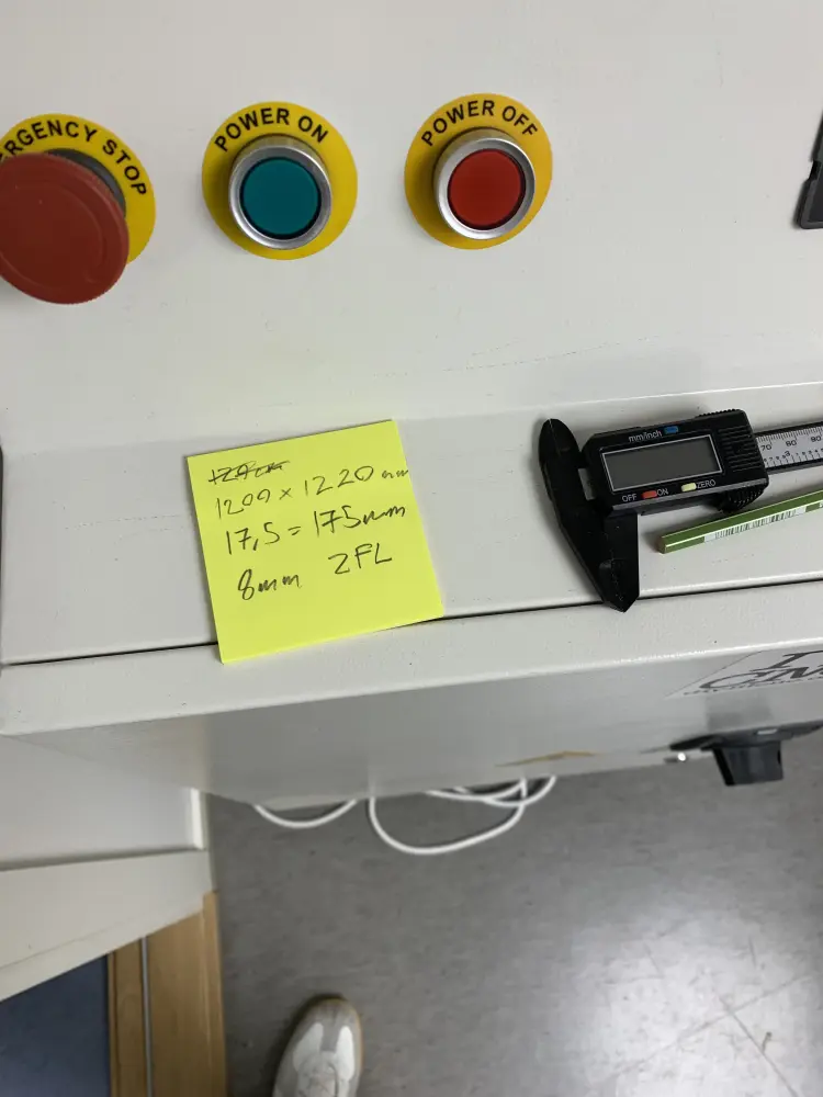
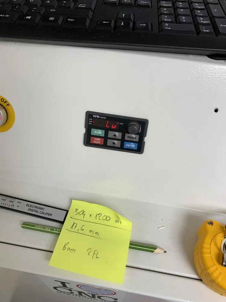
To start off, I carried the plywood from the storage over to the machine for measurement. This stuff is pretty rough, so it's a good idea to wear some gloves so that you don't get splinters or cuts. I measured the true width and height of the material, which ended up being around 1200mm x 1220mm. I also measured the thickness of the material, which came to around 17.5-17.6mm. I ended up using 17.5mm just to be sure.
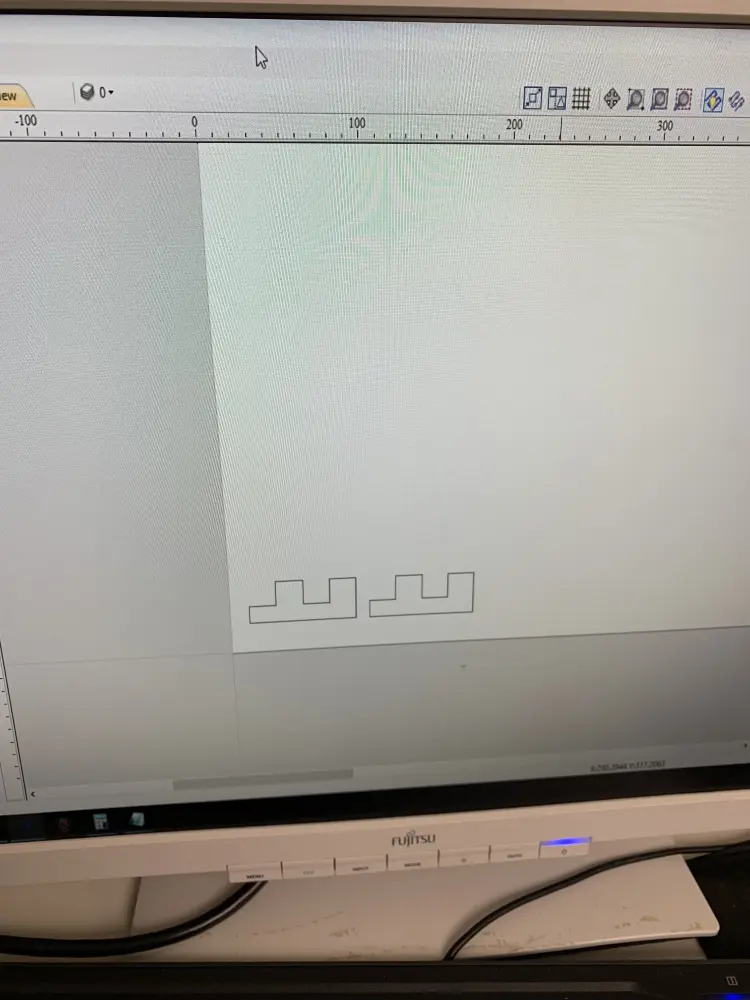
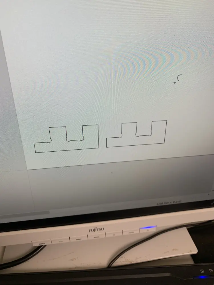
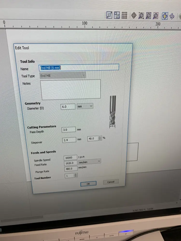
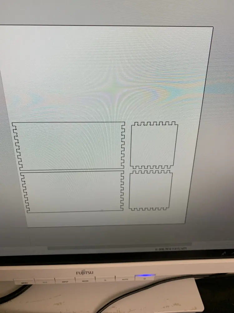
I then opened up VCarve, entered the plywood dimensions, and imported my test piece vectors from the .dxf file. I copied the vector once two cut out two pieces, and then added some Dog-Bone fillets. After this I went on to generate the tool paths, making sure to input the right tool parameters for a 6mm 2-flute milling bit.
For the pass depth you should use half of the bit diameter, and for the Stepover 40% is fine. To get the feed rate I used the formula Kris showed us, where you get the feed rate by multiplying to chip load of the bit (you get this from the manufacturer datasheet) by the number of flutes on the bit and the spindle speed. So in my case it was 0.06 * 2 * 16000 = 1920. For spindle speed around 2000rpm of the max speed of the machine is good. As for the plunge rate, I actually have no recollection how to calculate that. Will have to check.
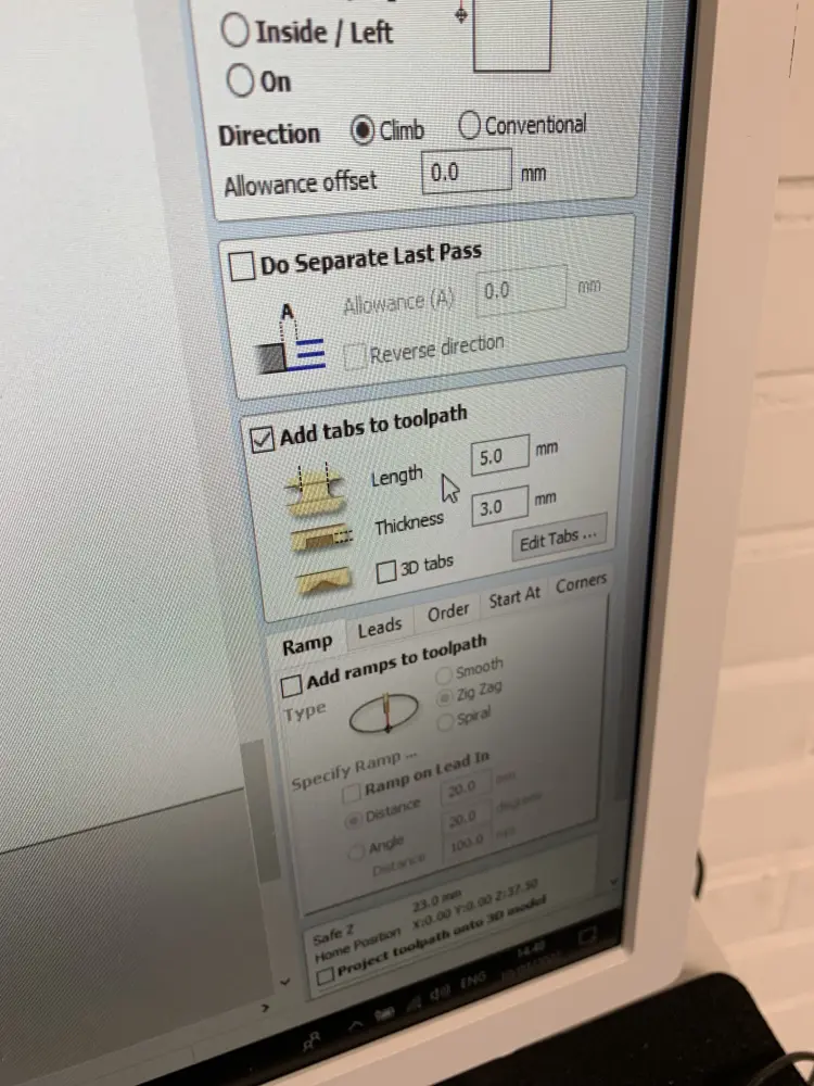
After checking that the tool parameters were set up correctly, I added tabs manually to to prevent the pieces from moving around when cut out. It later turned out that for some reason my tabs were really thin, and ended up snapping during the cutting process already. This wasn't really an issue though, luckily. Mostly because parts of the cut didn't end up going through and thus kept the design in place.
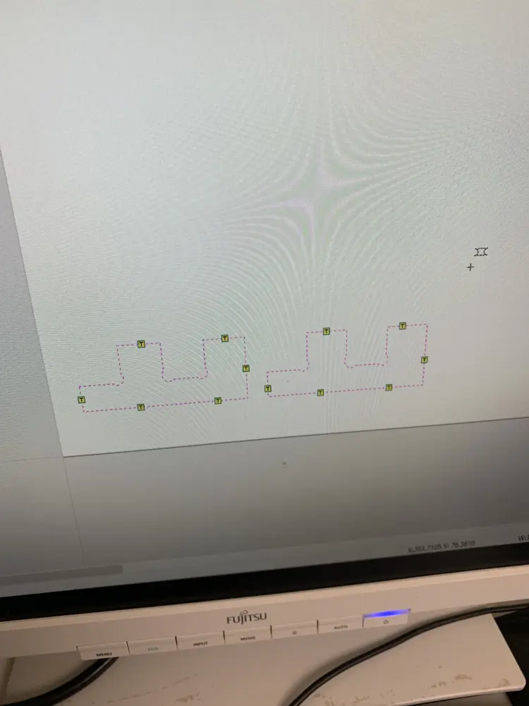
After this I generated the tool paths, checked that they were okay, and exported them. Next up was getting the machine ready for milling.
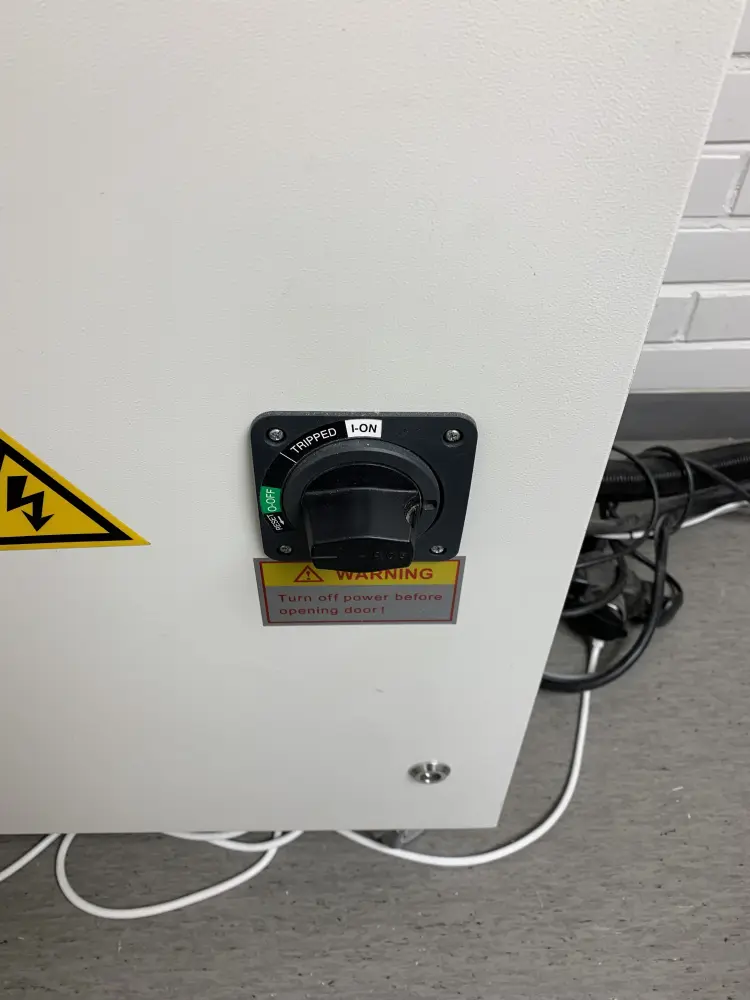
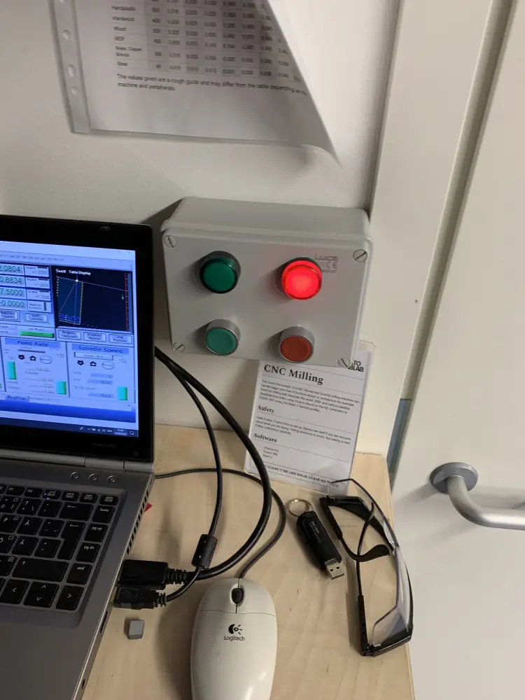
I started off by turning the milling machine on by flipping the tripper switch to "ON" and pressing the big green button that says "POWER ON".
After this I opened Mach3. I first hit "Reset", made sure "Soft Limits" had a green outline and hit the button that reads "REF ALL HOME". After this the machine was mostly calibrated, and I could move the milling head around freely. I moved it to the front for easier access when installing the machining bit.
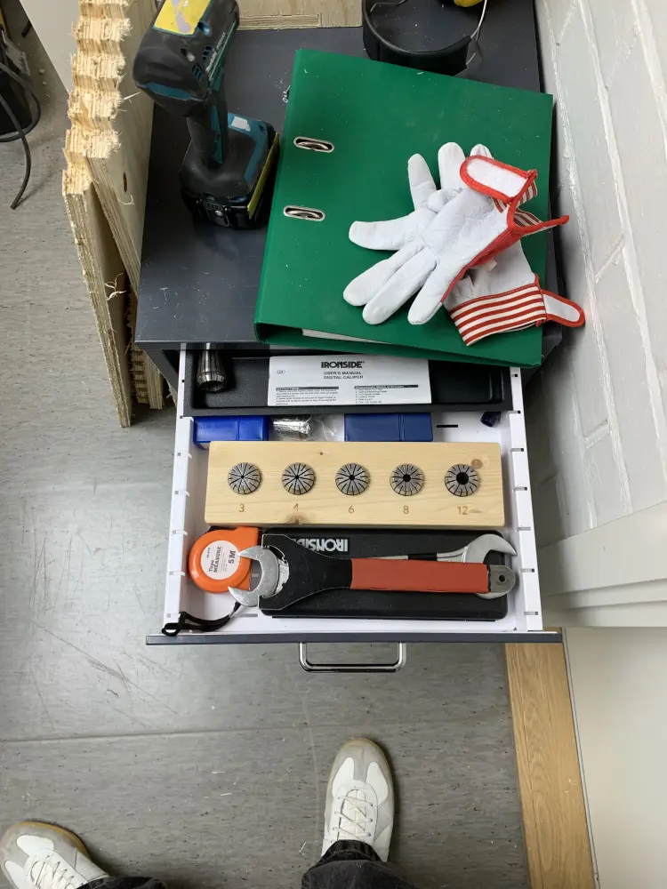
To install the milling bit, I chose the appropriate (6mm) collet from the collet drawer, and inserted the milling bit, leaving about a centimeter between the collet and where the flutes begin.
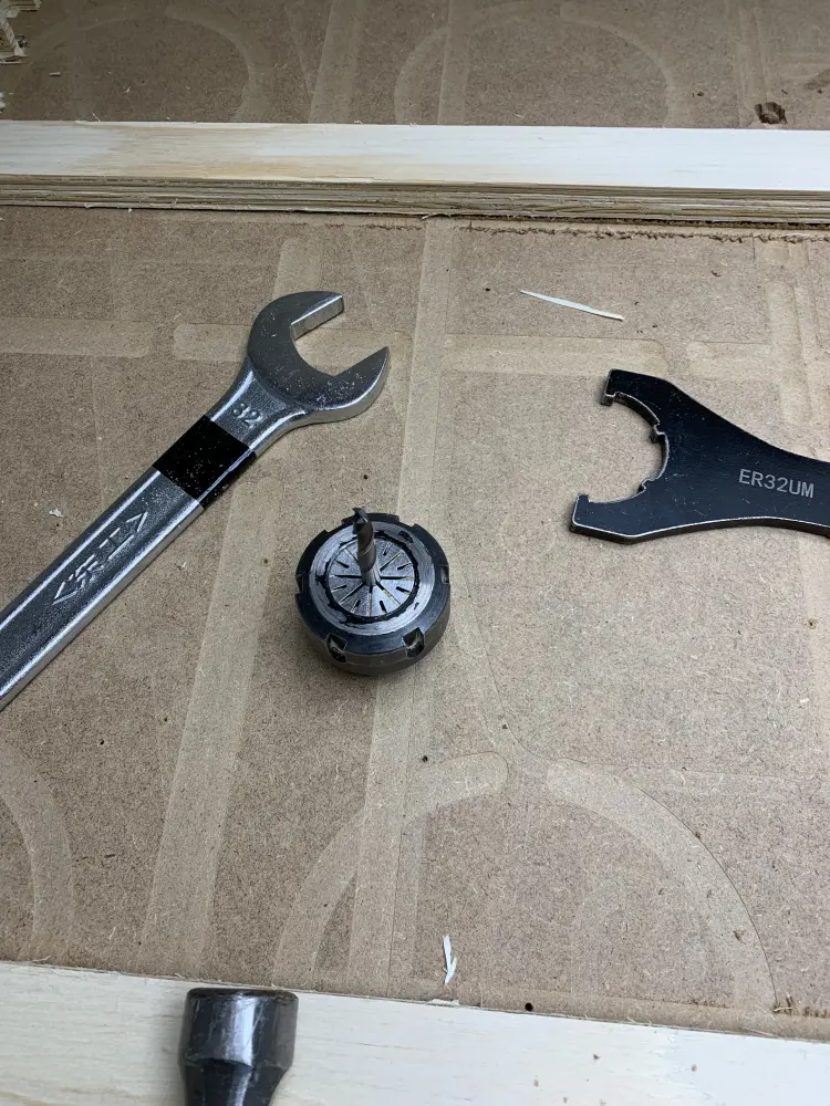
Then I placed the collet on the piece that tightens it to the machine head, and tightened it using the 32mm wrench while holding the collet in place with the special tool.
After the bit had been tightened, it was time to calibrate the Z axis. I took a sacrificial board and made sure to arrange the rubber bands on the cutting bed in a manner that would get a good seal with the vacuum pump. After this I placed the sacrificial board on the cutting bed, and then magnetic measurement thingy on the board.
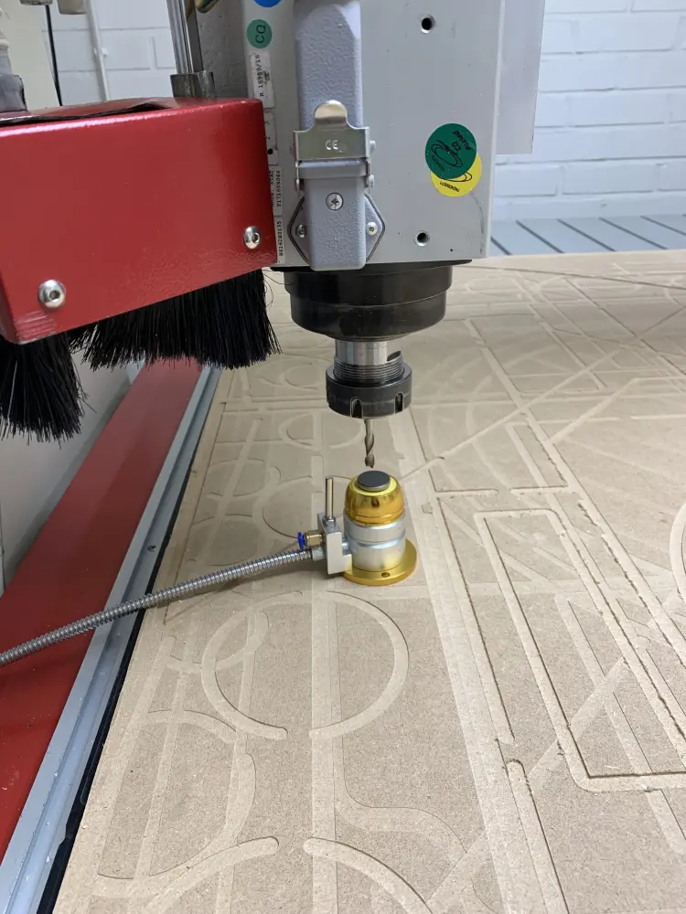
I then activated the vacuump pump (making sure to have ear protection on because that thing is pretty loud), moved the milling bit on top of the measurement device and pressed "Terän mittaus" in Mach3. This automatically measures and sets the Z origin.
After this I was ready to cut. I placed my material on the print bed, making sure to press it down to get a good seal with the vacuum. Then, as a final step, I attached the chip extractor to the machine head.
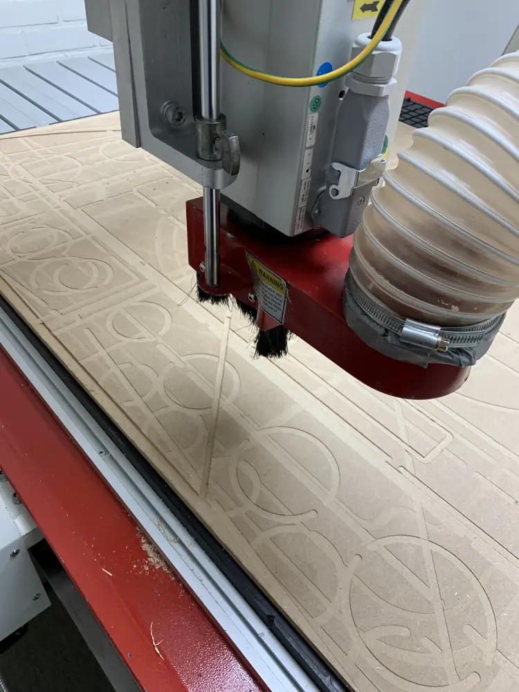
After this I was ready to cut, so I exited the room, loaded up my G-Code into Mach3 and pressed the big cut button in the wall.
AAnd when the machining bit touched the plywood the plywood just moved around freely. So I finally got to hit the big red button to cancel the job. After this I moved the bit out of the way, tried to fix the vacuum seal, tried again, and failed again.
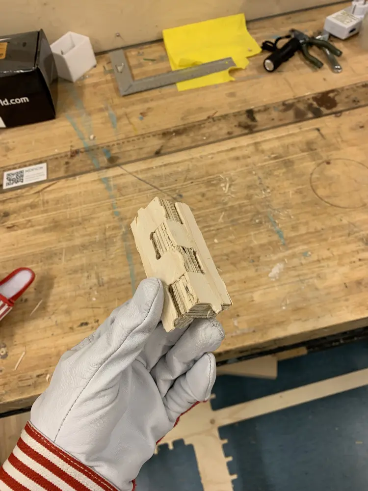
I asked Kris for help, and he suggested securing the plywood to the sacrificial board with screws, as the plywood was noticeably carved. After doing this. The plywood stayed in place (yay!) and I got my test cuts done.
Luckily the finger joints seemed to be alright, and went in fine with a bit of hammering:
Since the finger joints seemed to be working, it was time to proceed with the actual cutting of the shelf:
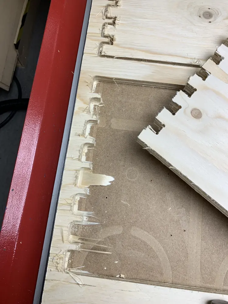
The final cut went mostly fine. Turns out that the plywood was so bent so that it actually pulled up the sacrificial layer as well. This meant that my cuts went through in the middle (even cutting through the tabs), but from the sides the material wouldn't be cut all the way through. It wasn't much of an issue as I could get the cut finished with a chisel, but it did result in some chips in the surface. Not sure how one would go about fixing this, except getting better material.
After this all that was left was to unscrew the plywood from the sacrificial board (didn't even strip any screws!) and to clean up the CNC workstation, making extra care to turn off the machine from the red button, waiting for the screen to say "Lo", and then flipping the tripper switch to "OFF".
Then I proceeded to the woodworking lab to finish up my pieces and put together the shelf. Should be easy enough, right?
Well, turns out that my finger joints were too tight for some reason, and I had to do quite a lot of dremeling and sanding to get them to fit. Definitely a lesson for the future. Either to be more careful or to avoid finger joints altogether.
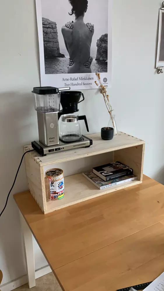
In the end I did manage to get my shelf together, and I'm quite pleased with the end result. I would like to know how to work with finger joints properly, but I guess that comes with time and experimenting.