Week 12: Output Devices
This week our assignment was to:
- Add an output device to a microcontroller board you've designed, and program it to do something.
- Measure the power consumption of an output device.
- Include a hero shot and source files of your board in your documentation.
- Submit a link to your assignment page here.
I already had a prototype of my final project outputting images to a CRT TV, so that's what I'll be documenting here.
The board
The board I'm going to be using is the ATtiny412 development board I made during the embedded programming week. It allows me to program the ATtiny via USB and has headers connected to the pins of the ATtiny to make connections easier.
Basics
The basic idea is to output a PAL TV signal from the development board to a CRT TV. PAL is an standard for transmitting analog video encoded into a single voltage signal. Because the signal is analog, we need to be able to output voltages other than ON or OFF, and thus we need a DAC (digital to analog converter). Luckily, the ATtiny has a built in DAC, which can output analog signals from the pin PA6. The basic workflow is as follows:
- Figure out how to output stuff using the DAC
- Figure out what to output and when
DAC
For the purpose of this assignment, I'm going to be using raw C with the avr-libc libraries. This is simply to make sure that I don't run into possible performance issues when trying to output the signal. I'm not going to go through how outputting to pins or other basic stuff works when using plaing C. I will however explain what I'm doing in each code segment.
Before writing to the DAC, we need to set what is called the reference voltage, i.e. the upper limit of voltage that gets outputted from DAC pin. For my purposes, I set this to 1.1V, because PAL operates between 0 and 1 volts, to my knowledge.
// Set reference voltage 1.1V (the upper limit of the DAC)
VREF.CTRLA |= VREF_DAC0REFSEL_1V1_gc;
Next we need to enable DAC output by setting both the OUTEN and ENABLE bits of the DAC control register to 1. I've also cleared the DAC_DATA register before doing this. Not sure if it's strictly necessary, but it makes sure that we don't transmit any data that we might not want to.
// Clear DAC data register, just to be sure.
DAC0_DATA = 0;
// Enable DAC output to a pin by setting the OUTEN and ENABLE bits to 1
DAC0_CTRLA |= 0x41;
Now we are ready to output analog signals via the DAC. Doing this is really simple, simply write
DAC0_DATA = <value>
where <value> is a number between 0 and 255.
PAL Signal
Now that we have the DAC running, we need to figure out what values we need to write there, and when. It's a good idea to chop the concept of displaying an image into smaller pieces, so I started by writing code that outputs a scanline and all the relevant syncing signals. This required me to check the PAL timings for a scanline:
| Area | PAL | NTSC |
|---|---|---|
| Whole Scanline | 64μs | 63.55μs |
| Front Porch | 1.65μs | 1.5μs |
| H-Sync pulse | 4.7μs | 4.7μs |
| Back Porch | 5.7μs | 4.5μs |
| Blanking period (total) | 12.05μs | 10.7μs |
| 'Active Display' period | 51.95μs | 52.9μs |
A scanline starts with a horizontal blanking period, followed by the actual image data. The horizontal blanking period lasts for 12.05µs, and consists of three parts: the front porch (1.65µs, the H-Sync pulse (4.7µs) and the back porch (5.7µs). In practice this translates to 1.65µs of 0.3V (black level), 4.7µs of 0V (SYNC level) and 5.7µs of 0.3V again. Let's write code for that:
#define SYNC_LEVEL 0
#define BLACK_LEVEL 70 // or 69.5
#define WHITE_LEVEL 255

void horizontal_blank() {
  DAC0_DATA = BLACK_LEVEL;
  _delay_us(1.65);
  DAC0_DATA = SYNC_LEVEL;
  _delay_us(4);
  DAC0_DATA = BLACK_LEVEL;
  _delay_us(5.7);
}
Since the range for the DAC data is from 0 to 255, we need to convert the voltage values to these. The sync and white levels (max voltage) are pretty self explanatory, but to figure out the black level (0.3V), I had to use some math: black level = 0.3 * (255 / 1.1).
Now that we have the horizontal blanking down, we can move to the active display period of the scanline, which lasts for 51.95µs. I wanted to output half black and half white for each scanline, so here's what my code for a scanline ended up looking like:
void print_scanline() {
  horizontal_blank();
  _delay_us(25.975);
  DAC0_DATA = WHITE_LEVEL;
  _delay_us(25.975);
}
That should take care of printing an individual scanline. Now we need to add the vertical blanks used for separating frames. To simplify things, we aren't going to be interlacing, which is done by default in PAL. Instead we are going to write 304 scanlines and 8 scanlines worth of vertical blanking, resulting in 312 scanlines in total.
To start a frame, non-interlaced PAL requires us to have 6 "long syncs" (30µs of 0V and 2µs of 0.3V) and 5 "short syncs" (2µs of 0V and 30µs of 0.3V). Let's write this out:
void short_sync() {
  DAC0_DATA = SYNC_LEVEL;
  _delay_us(2);
  DAC0_DATA = BLACK_LEVEL;
  _delay_us(30);
}

void long_sync() {
  DAC0_DATA = SYNC_LEVEL;
  _delay_us(30);
  DAC0_DATA = BLACK_LEVEL;
  _delay_us(2);
}

void start_of_frame_vertical_blank() {
  for (int i = 0; i < 5; i++) {
    long_sync();
  }

  for (int j = 0; j < 5; j++) {
    short_sync();
  }
}
In addition to this, we need to do another vertical blank at the end of the frame, this time consisting of 6 short pulses:
void end_of_frame_vertical_blank() {
  for (int i = 0; i < 6; i++) {
    short_sync();
  }
}
Now that we have all the parts of a frame, we can output them:
for (;;) {
  start_of_frame_vertical_blank();
  for (int y = 0; y < 304; y++) {
    print_scanline();
  }
  end_of_frame_vertical_blank();
}
Testing
Now that we have the code for displaying PAL video successfully uploaded to the microcontroller, it was time to test it. I was hesitant to plug it into a TV straight away, so instead I used an oscilloscope to see if the timings and the general appearance of the signal looked about correct.
To do this, I used the development headers I have on my board. I attached the ground of the oscilloscope probe to the ground of my development board, and the actual probe to the header connected to the DAC pin.
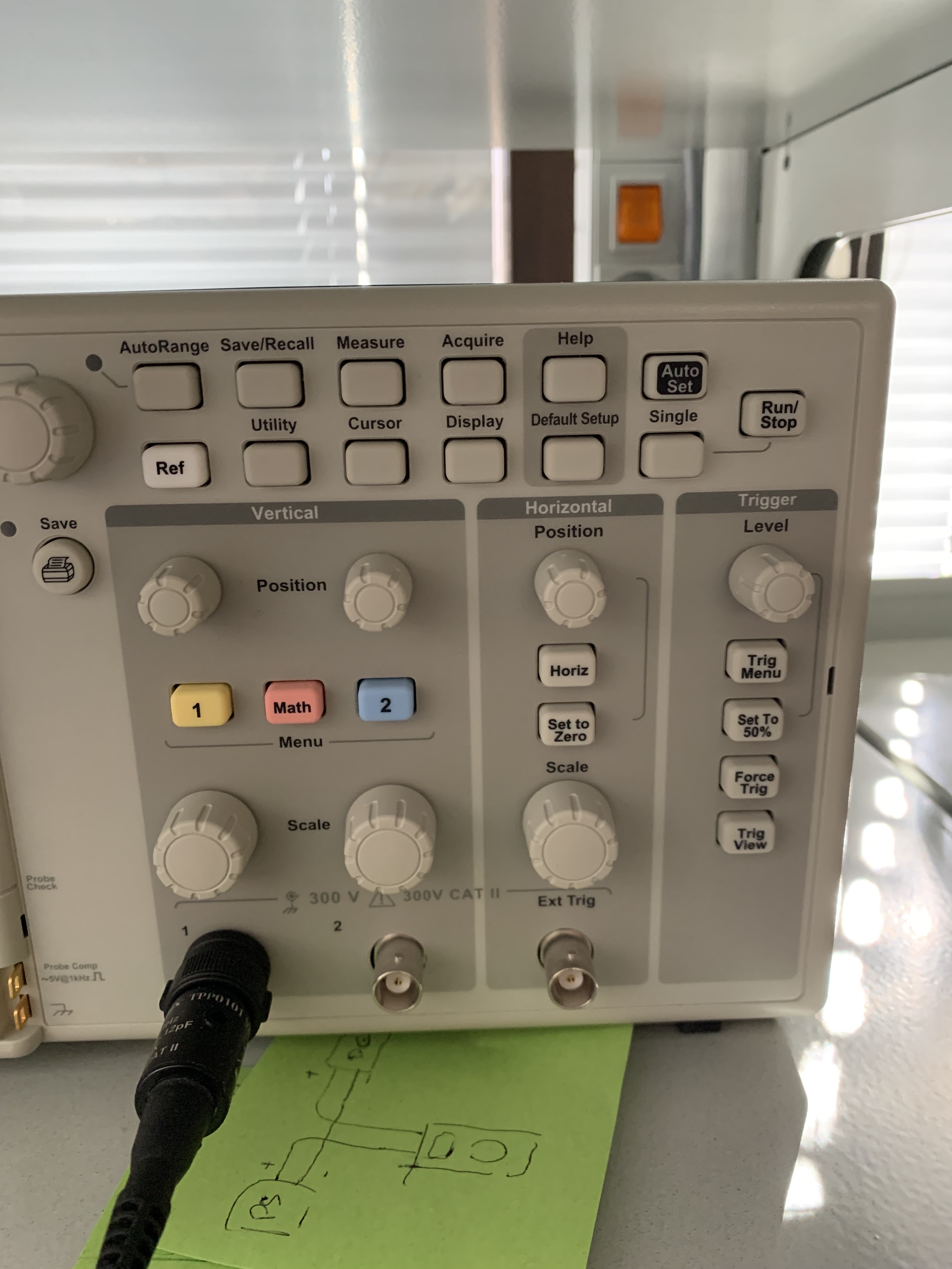
To use an oscilloscope, you adjust the vertical/horizontal position and scale using the knobs in the front panel. By scaling down to roughly the timescale and amplitude you're expecting can give you some idea if your signal is correct or not. However in my case, the timings of the pulses in the signal are so quick, that I needed a more accurate way to estimate timings of my signal. Enter cursors.
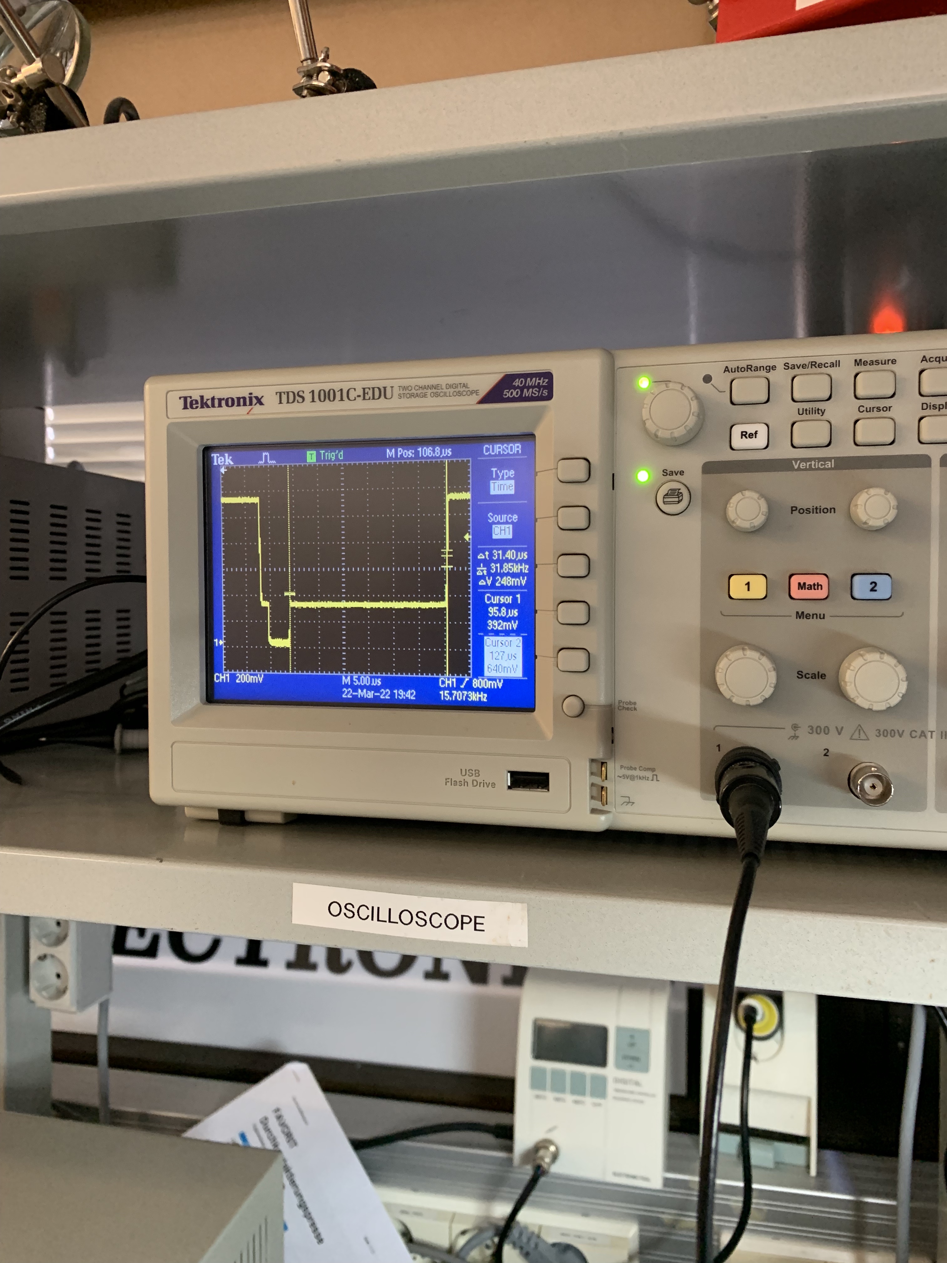
To place cursors on the waveform, you press the "Cursor" button on the oscilloscope. Then you can choose whether you want to place cursors horizontally (Type: Time) or vertically (Type: Amplitude). Then you highlight each cursor using it's respective button, after which you can move the cursor to it's desired position using the multipurpose knob. After the cursors have been placed, the oscilloscope will tell you the difference between the two cursors. Here you can see that I've placed cursors at the start and end of a scanline to verify that the length of the scanline is 64µs:
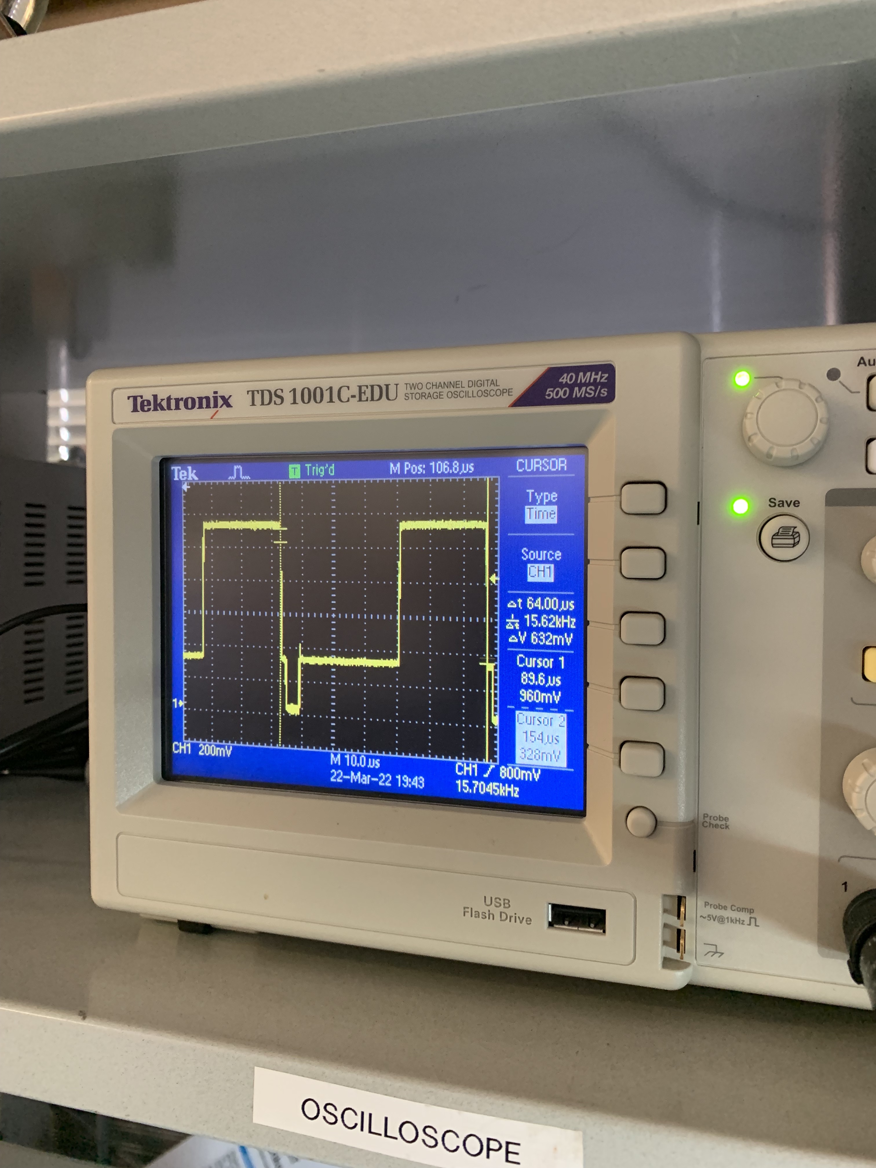
This helped immensely to verify that my sync pulses and whatnot were actually timed right, and made me feel a lot more confident about the whole thing.
One other neat feature in the Tektronix oscilloscope we have at the FabLab is the Video mode. This enabled me to view the waveform and move around it without it constantly moving in and out of view like would happen in the Edge measurement mode.
Results
After testing with the oscilloscope, I plugged my board into a CRT TV and what do you know, I was getting a signal out!