Week 08: Electronics Design
Our assignments this week were to:
- Use the test equipment at the Fablab to observe the operation of a microcontroller circuit board: check operating voltage on the board with multimeter or voltmeter; use oscilliscope to check noise of operating voltage and interpret a data signal.
- Redraw one of the echo hello-world boards or equivalent and add (at least) a button and a LED (with current limiting resistor) or equvivalent input and output, check the design rules, make it, test it.
- Document your process in a new page on your website.
- Submit a link to the page on your documentation website.
PCB Design
For designing I used KiCad, as that is what Kris went through in the lecture. I pretty much sketched the exact board that Kris showed, that is the Hello ATtiny412 board, except that mine has a button and two LEDs. It also has a missing diode, but more on that later.
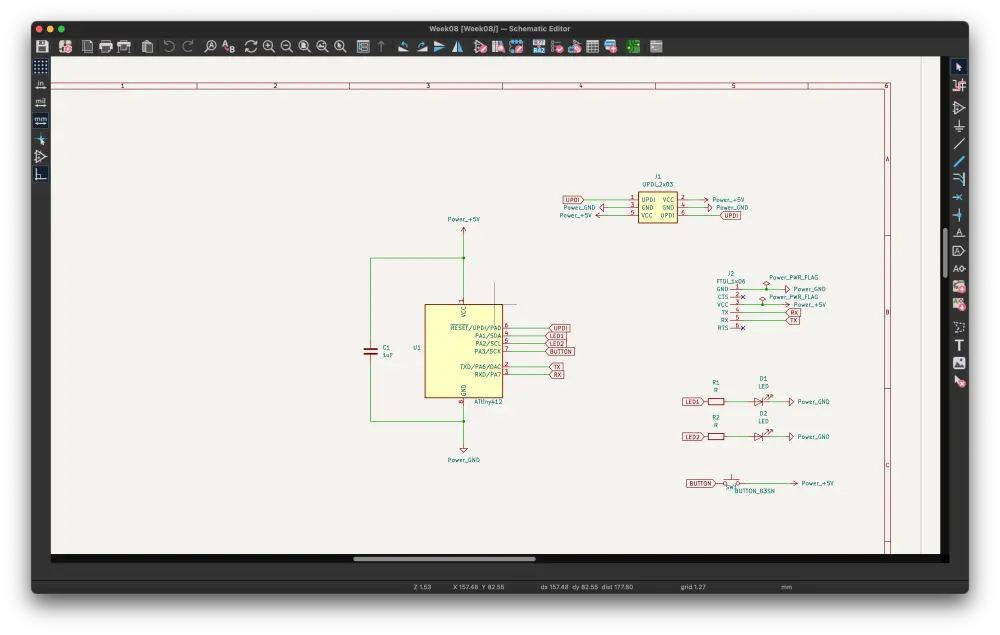
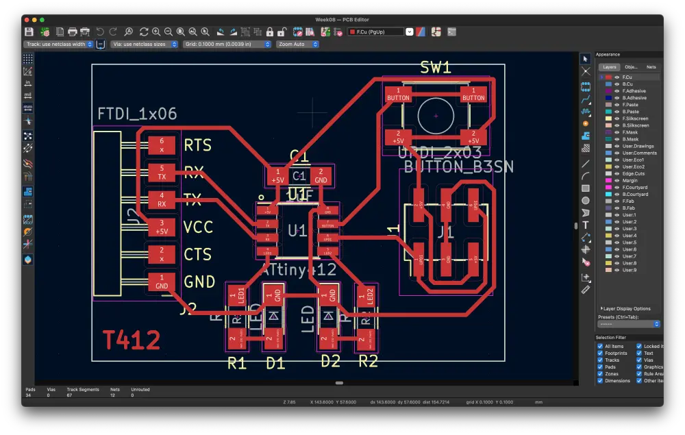
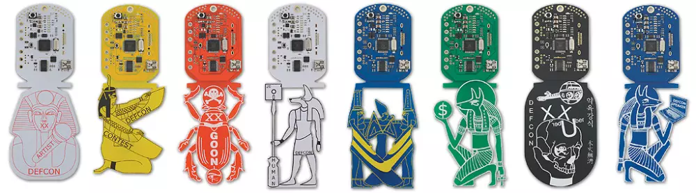
Otherwise designing the board went without a hitch, except that for some reason I routed the button to 5V instead of GND, which is incorrect. I actually really liked designing boards in KiCad, even if creating traces between components is a bit of a mental exercise at times. I'd really love to get into more creative PCB design at some point, like these DefCon badges below, but it will require a lot more learning and also (probably) getting the boards manufactured elsewhere, since graphics are usually silkscreened, I guess.
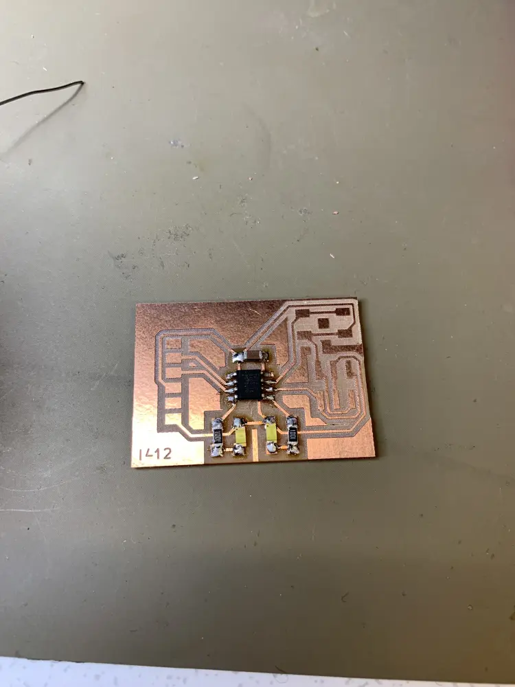
PCB Milling
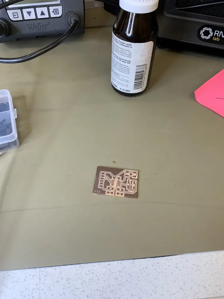
Milling the PCB was already familiar to me from a previous week. Nothing really went wrong here, except that CopperCam refused to mark all of the text as centerlines, resulting in broken text being engraved. Otherwise all the traces got engraved nicely and the board got cut out of the copper plate succesfully. 👍
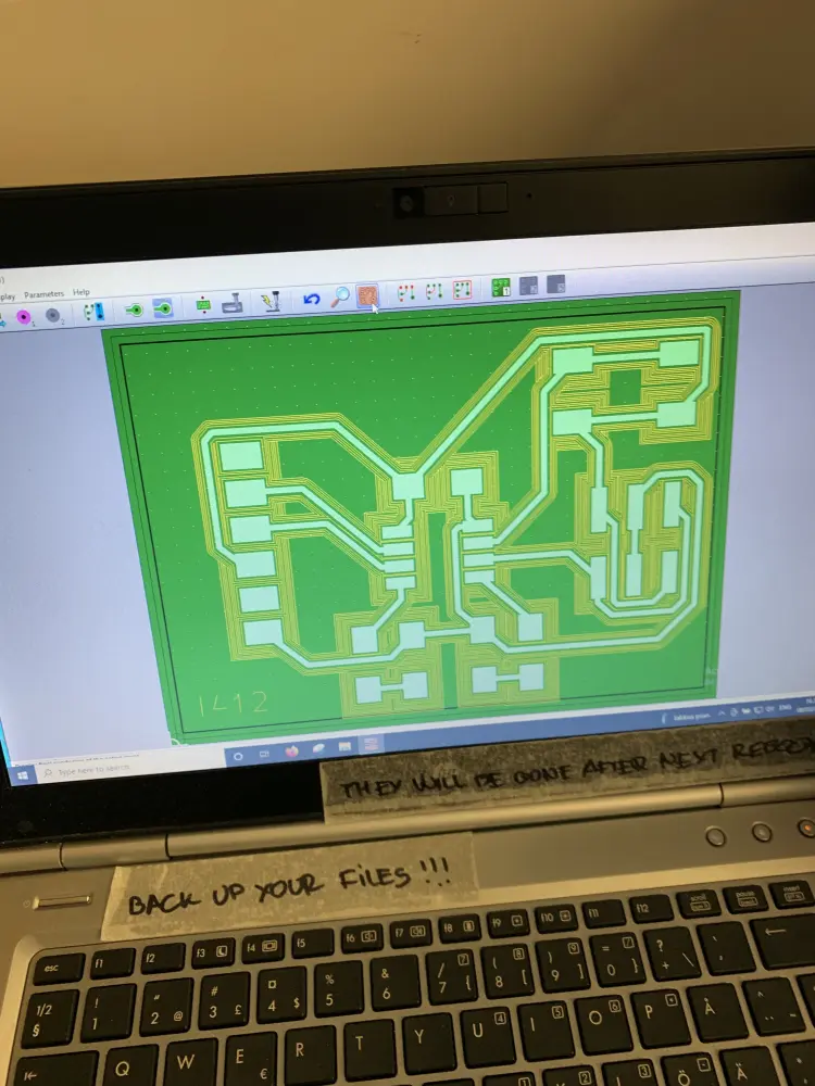
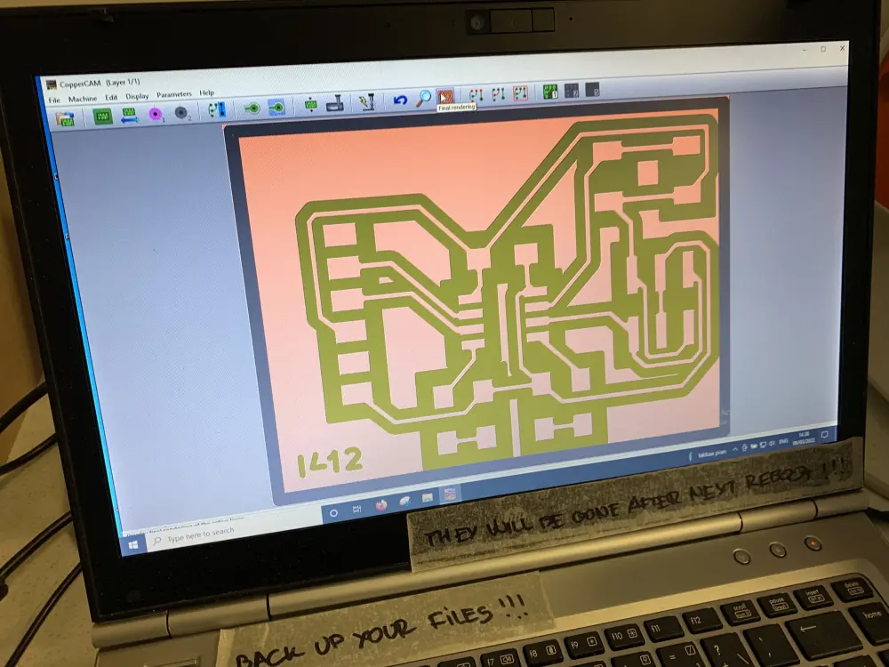
One thing I would like to learn is carving out all the excess copper out of the board so that only the traces and pads remain. This would imho result in a cleaner result, although it undoubtedly would take a lot more time, which at the moment is a resource I don't exactly have the luxury of wasting. Maybe later!
Soldering
I approached soldering the same way I approached it during the Electronics Production -week. I started out by scraping off some of the smaller excess copper parts and cleaning the board with isopropyl alcohol.
Then I checked out the interactive BOM of the Hello ATtiny412 board to check out what parts I had to get. It was at this point that I realized that I had failed to add a Schottky diode to the board, as this was skipped during Krises lecture. I checked with Matti, since he happened to be at Fab Lab at the same time, and he said it shouldn't matter as long as I take extra care not to use the FTDI and UPDI connectors at the same time.
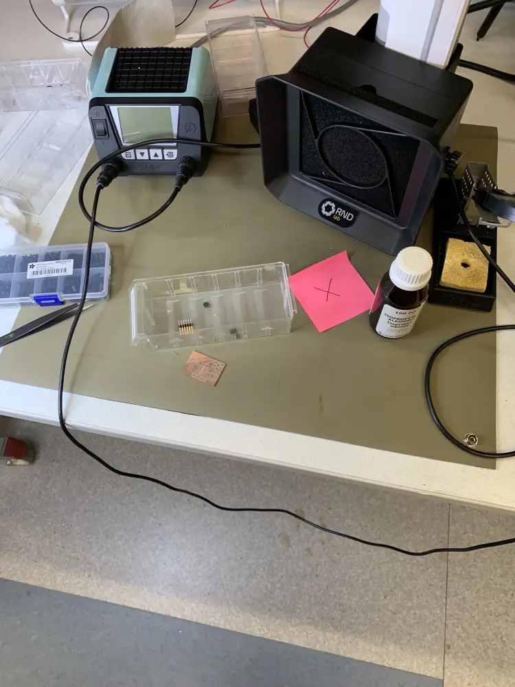
I carried on by gathering all the components I needed for the board:
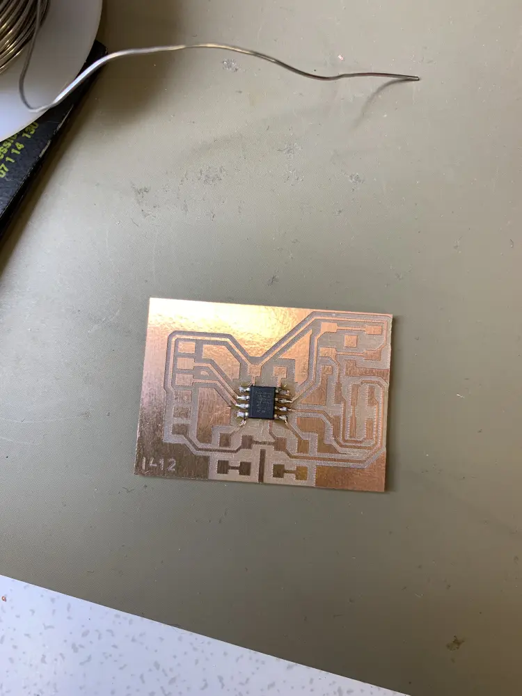
I started soldering from the ATtiny chip. I checked the orientation from the demo board on Kris's table, as I still don't trust myself enough to remember which one is pin 1 just from looking at the chip.
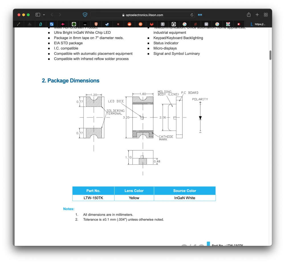
Then I went on and soldered the capacitor, the LEDs and the resistors. I had to check the datasheet for the LEDs to check for their orientation. The side with the dot is the cathode side, which apparently means negative. Would love to know how diodes actually work, and what is a cathode. Anyways, I've kinda been afraid of looking at datasheets for some reason, so this definitely was good practice.
After this only the big stuff remained: the button and the headers. I started with the button, but in hindsight starting with the 2x3 header would've been smarter, as the button got a bit in the way when soldering the 2x3 header. Matti gave me a tip to tin the feet of the button before soldering it in place, so I did it for the foot I was planning on soldering first.
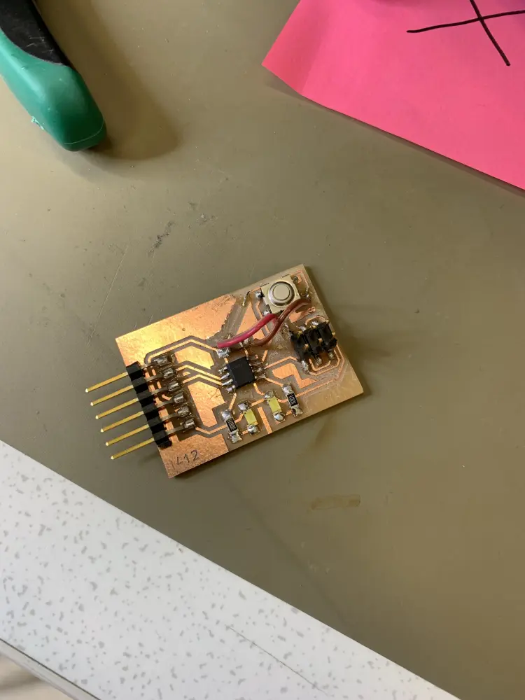
Then I did the usual: melted solder on the pad, aligned the button, melted the solder on the pad, and ta-da, first pin of the button soldered. Then I hit the rest of the feet with solder, and also soldered on the two headers:
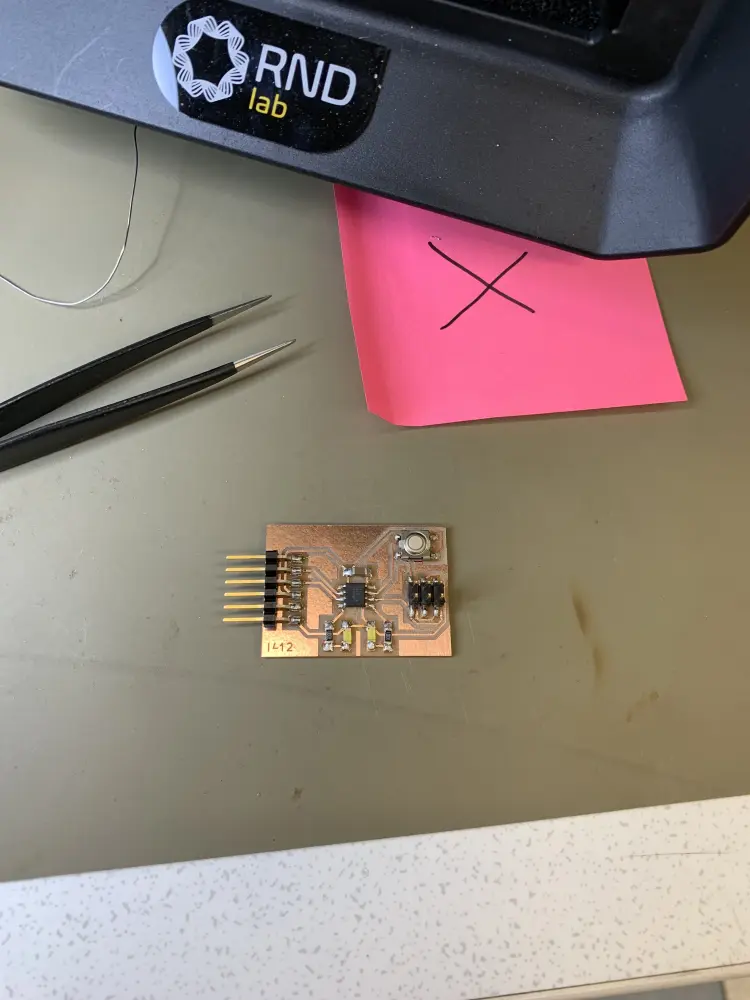
At this point the board was completed, and I even managed to avoid shortcircuits. I feel like I'm getting the hang of it, feel super good!
Testing the board
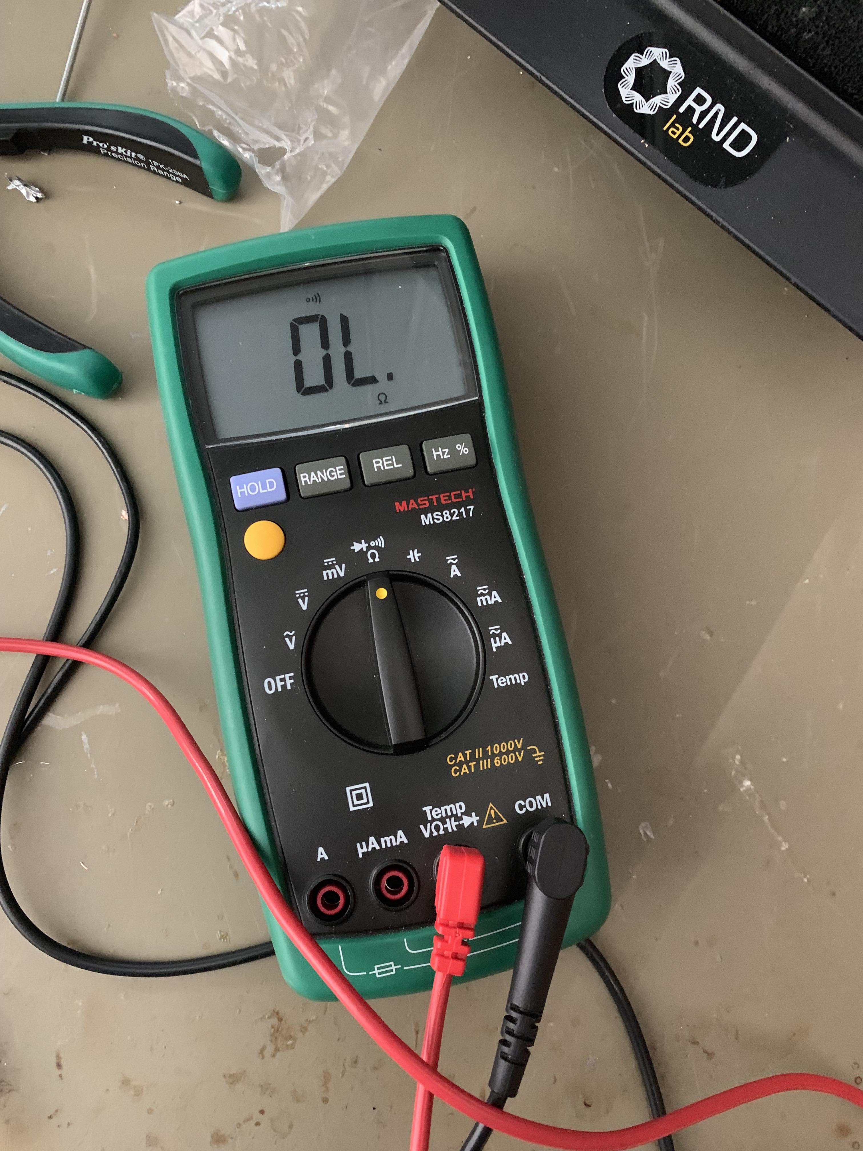
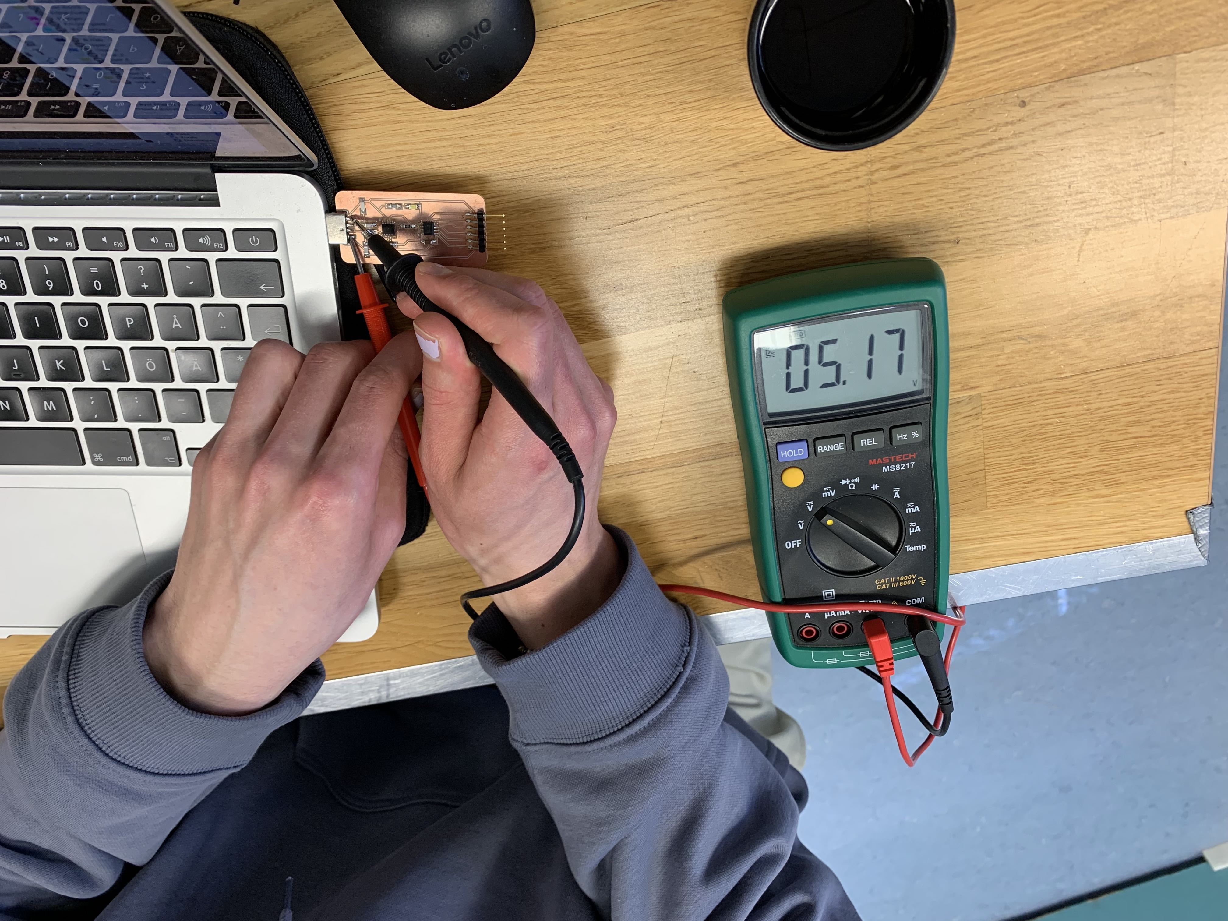
It's important to test your board before for shorts before trying to give it power, so that you avoid breaking any components. The way I usually do this is with a multimeter. Set the multimeter to the connectivity mode, and press the yellow button a few times to get the beep symbol on the screen. Now you can use the two leads of the multimeter to check if any two spots on the board are connected. The multimeter will beep if there is a connection.
You can also use the multimeter to check the voltage running through the chip once it's powered. To do this set the multimeter to the V symbol with the straight and dotted lines. Then place the black lead in the ground and move the red lead around to see the voltage running through the chip. If you're getting negative voltage, it means you have the leads the wrong way around.
Using an oscilloscope
Check Week 12: Output Devices.
Programming
To program the board, I used Mattis UPDI programmer (thanks Matti!) because I had forgot mine at home. At first I had some issues, but they turned out to be due to the UPDI programmer not having the correct code uploaded.
To start off with I uploaded code to test both of the LEDs:
This turned out to be a success, as is evident from the video. Had I really managed to design, mill and solder a working board without so much as breaking a sweat? Of course not. It was when I tried using the button as I began to ran into issues. Using the input mode INPUT_PULLUP and copying code from Electronics For Artists I could not get the led to toggle when pressing the button.
I took a FTDI board from Kris's table to be able to check what the board was logging into the serial output. Turns out that the button state was always 1. This meant that the two sides were already connected somehow. With the help of Matti, I was able to figure out that the GND side of my button was actually connected to 5V due to me designing it wrong for some reason 😬😬. Matti suggested to cut the traces from the button and use wire to jump it to GND, which is what I did. I also had to jump the 5v of the 2x3 header with a wire, as it was routed via the button previously. I think going forward I will definitely remember that the other pin of buttons is GND, not 5V.
The result is definitely not the cleanest, but hey, it works! And I also learned something in the progress.
Till next time!